Structure of capacitor set

a capacitor and set technology, applied in capacitors, semiconductor devices, semiconductor/solid-state device details, etc., can solve the problems of reducing product performance, costing more, and reducing the capacitance variation of the capacitor process, so as to reduce the capacitance variation and improve the product performance

Active Publication Date: 2010-06-10
MARLIN SEMICON LTD
View PDF14 Cites 3 Cited by
  • Summary
  • Abstract
  • Description
  • Claims
  • Application Information

AI Technical Summary

Benefits of technology

[0009]Accordingly, this invention provides a structure of a capacitor set that is capable of reducing the capacitance variation to improve the performance of the product.
[0010]This invention also provides a method for reducing the capacitance variation between capacitors, which makes the local capacitance variation decrease more effectively with an increase in the capacitor area as well as decreases the global capacitance variation.
[0018]In the above structure and method of this invention, at least two capacitors are partitioned into at least two groups of capacitor units, which are formed tangling with each other to form a 2D or 3D mesh structure that can lower the relative capacitance variation between the capacitors including both the local capacitance variation and the global capacitance variation. Thus, a capacitance mismatch problem can be prevented more effectively, and the performances of the products can be made more uniform.

Problems solved by technology

On the contrary, a MIM capacitor process needs an extra photomask and an extra lithography process, and therefore costs more.
However, the fabricating process of either type of capacitor is easily affected by some variation factors, such as machine wearing and changes in raw materials, so that the capacitances of the capacitors are not uniform causing a relative variation that lowers the product performances.
For example, through a capacitance match measurement to two capacitors in the same die, the capacitances of the two capacitors are found to be different causing a capacitance mismatch problem.
For MIM capacitors, increasing the capacitor area can effectively decreases the local capacitance variation; for MOM capacitors, however, increasing the capacitor area cannot effectively decreases the local capacitance variation.
Moreover; with an increase in the capacitor area, the long-range global capacitance variation is adversely increased, so that the performances of the products are difficult to make uniform.
Accordingly, the statistical capacitance variation between capacitors are a very important issue to the performance of IC products.

Method used


Image

  • Structure of capacitor set
  • Structure of capacitor set
  • Structure of capacitor set

Examples


Embodiment Construction

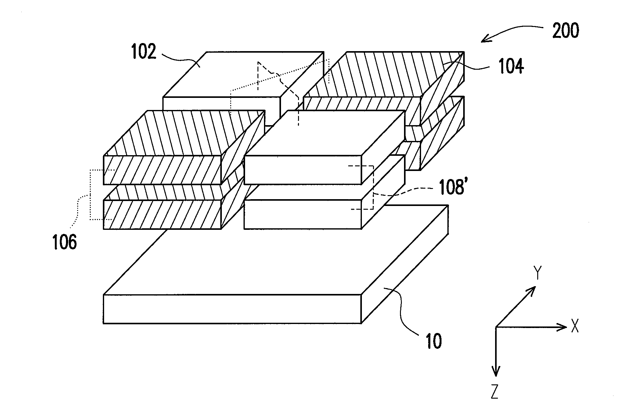
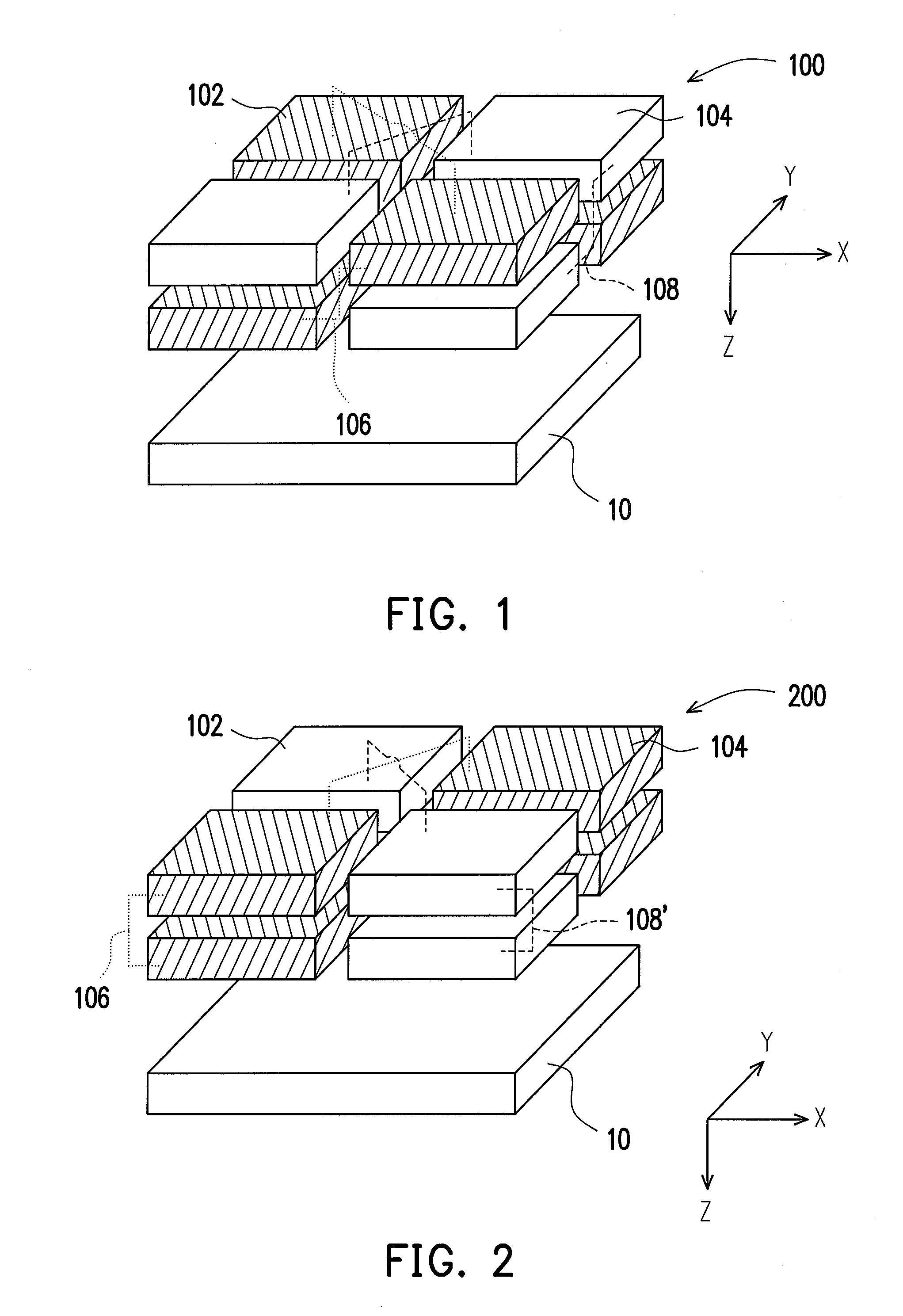
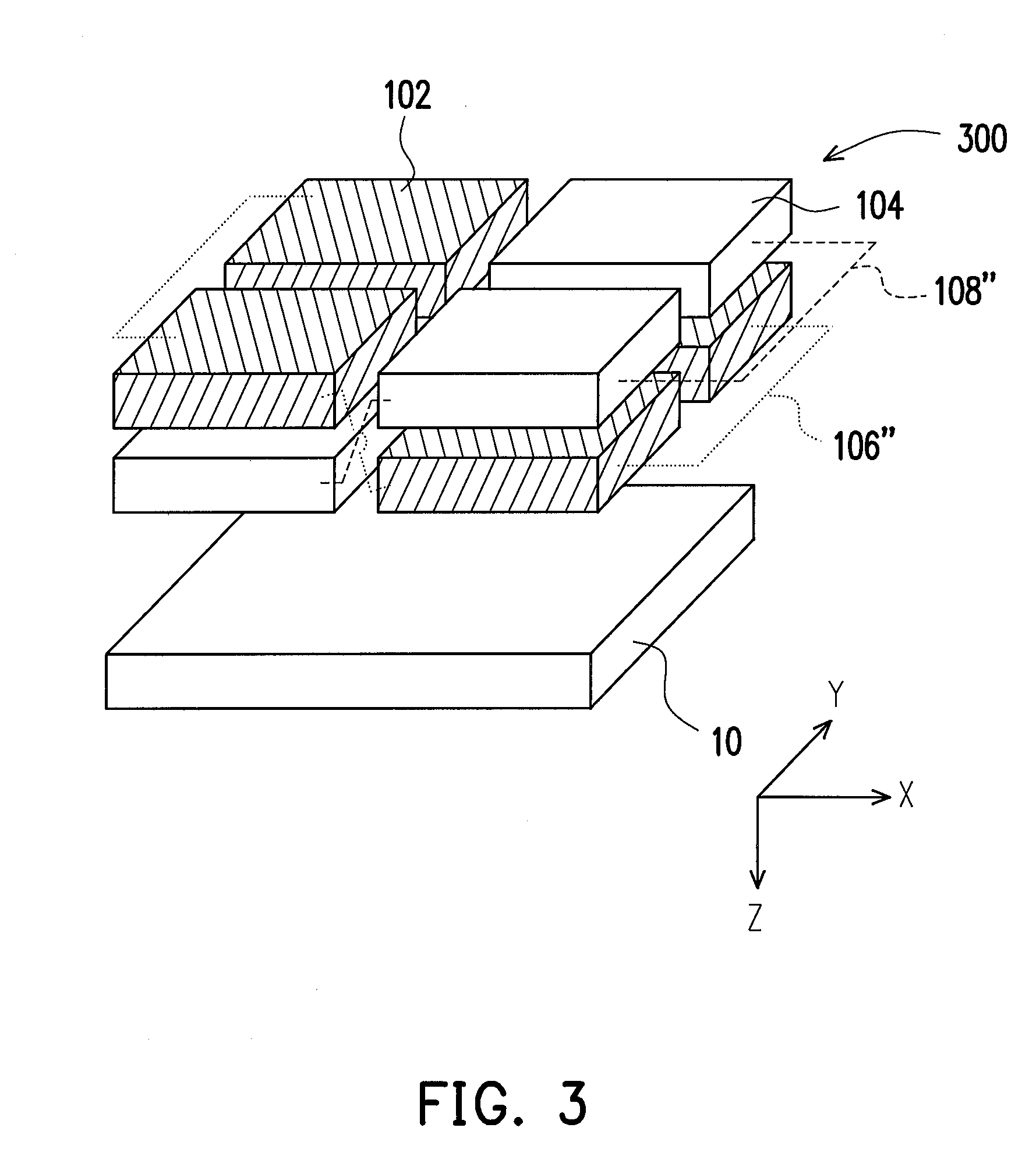
[0026]As mentioned above, the principle of reducing the capacitance variations in this invention is to partition each of at least two capacitors with the same capacitance into a group of capacitor units and then arrange and spatially intermix different groups of capacitor units into an array with the capacitor units of the same group electrically connected with each other in parallel. In a preferred embodiment, the capacitor-unit numbers of all of the groups are the same, and the capacitances of all of the capacitor units are also the same for all of the capacitors have the same capacitance.

[0027]The above capacitor set structure can effectively decrease the global capacitance variation, which is explained below in reference of FIG. 8 that shows an example of the capacitance varying with the position within a long range in the prior art. In FIG. 8, the capacitance curve 802 is fluctuant because of the local capacitance variation, and the dashed curve 804 represents long-range capaci...


PUM


Abstract

A structure of a capacitor set is described, including at least two capacitors that are disposed at the same position on a substrate and include a first capacitor and a second capacitor. The first capacitor includes multiple first capacitor units electrically connected with each other in parallel. The second capacitor includes multiple second capacitor units electrically connected with each other in parallel. The first and the second capacitor units are arranged spatially intermixing with each other to form an array.

Description

CROSS-REFERENCE TO RELATED APPLICATION[0001]This application is a divisional of and claims the priority benefit of U.S. application Ser. No. 11 / 309,164, filed on Jul. 4, 2006. The entirety of the above-mentioned patent application is hereby incorporated by reference herein and made a part of specification.BACKGROUND OF THE INVENTION[0002]1. Field of the Invention[0003]The present invention relates to a structure of an integrated circuit (IC) device. More particularly, the present invention relates to a structure of a capacitor set, and to a method for reducing the capacitance variation between capacitors.[0004]2. Description of the Related Art[0005]The capacitor is one of the major devices in integrated circuits. In applications of analog devices, the capacitors usually used include the metal-insulator-metal (MIM) capacitor and the metal-oxide-metal (MOM) capacitor. The fabricating process of a MOM capacitor can be integrated with the interconnect process, hence needing no extra pho...

Claims


Application Information

Patent Timeline
Patent Type & Authority Applications(United States)
IPC IPC(8): H01L29/92
CPCH01L23/5223H01L28/87H01L28/91H01L2924/0002H01L2924/00
Inventor LIANG, VICTOR CHIANGYANG, CHIEN-KUOTSENG, HUA-CHOUKO, CHUN-YAOFAN, CHENG-WENCHIANG, YU-HOTZENG, CHIH-YUH
Owner MARLIN SEMICON LTD
Why Eureka
Try Eureka