Magnetic Field Sensors and Methods for Fabricating the Magnetic Field Sensors

a magnetic field sensor and magnetic field technology, applied in the field of magnetic field sensors, can solve the problems of increasing the difficulty of accurately analysing the output reducing the accuracy of hall effect elements, so as to avoid an excessive increase in the effective air gap, avoid the loss of costly magnets, and ensure the effect of accuracy

Active Publication Date: 2010-06-10
ALLEGRO MICROSYSTEMS INC
View PDF81 Cites 95 Cited by
  • Summary
  • Abstract
  • Description
  • Claims
  • Application Information

AI Technical Summary

Benefits of technology

[0021]With the above arrangements, a packaging scheme for a magnetic field sensor provides reliable protection from the environment that avoids an excessive increase in an effective air gap between the associated magnetic field sensing element and the object to be sensed, that allows the magnetic field sensing element to be as close as possible to the magnet, and that does not result in loss of a costly magnet if the magnetic field sensor fails during manufacturing testing.
[0027]With the above arrangements, a packaging scheme for a magnetic field sensor provides reliable protection from the environment that avoids an excessive increase in an effective air gap between the associated magnetic field sensing element and the object to be sensed, and that does not result in loss of a costly magnet if the magnetic field sensor fails during manufacturing testing.

Problems solved by technology

More specifically, as the air gap increases, the output of a Hall effect element within the proximity detector, which is directly proportional to the strength of the magnetic field, decreases, making it more difficult to accurately analyze the output of the Hall effect element.
It is known that a magnet is relatively expensive.
The manufacture of conventional forms of proximity detectors does not allow the magnet to be reused or replaced once the molding step is completed.
Thus, if a conventional proximity detector fails manufacturing testing after molding, the cost of the magnet is lost in addition to the cost of the semiconductor die and packaging materials.

Method used


Image

  • Magnetic Field Sensors and Methods for Fabricating the Magnetic Field Sensors
  • Magnetic Field Sensors and Methods for Fabricating the Magnetic Field Sensors
  • Magnetic Field Sensors and Methods for Fabricating the Magnetic Field Sensors

Examples


Embodiment Construction

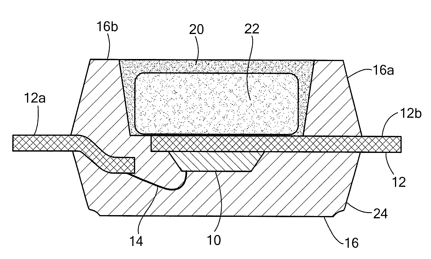
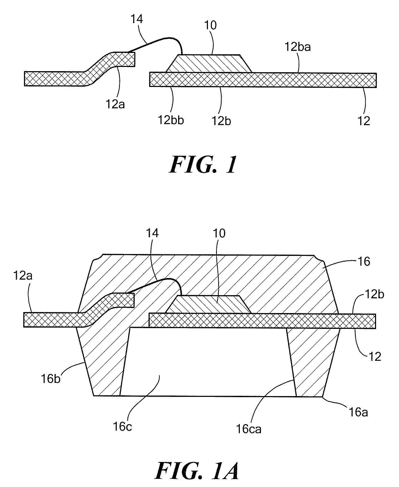
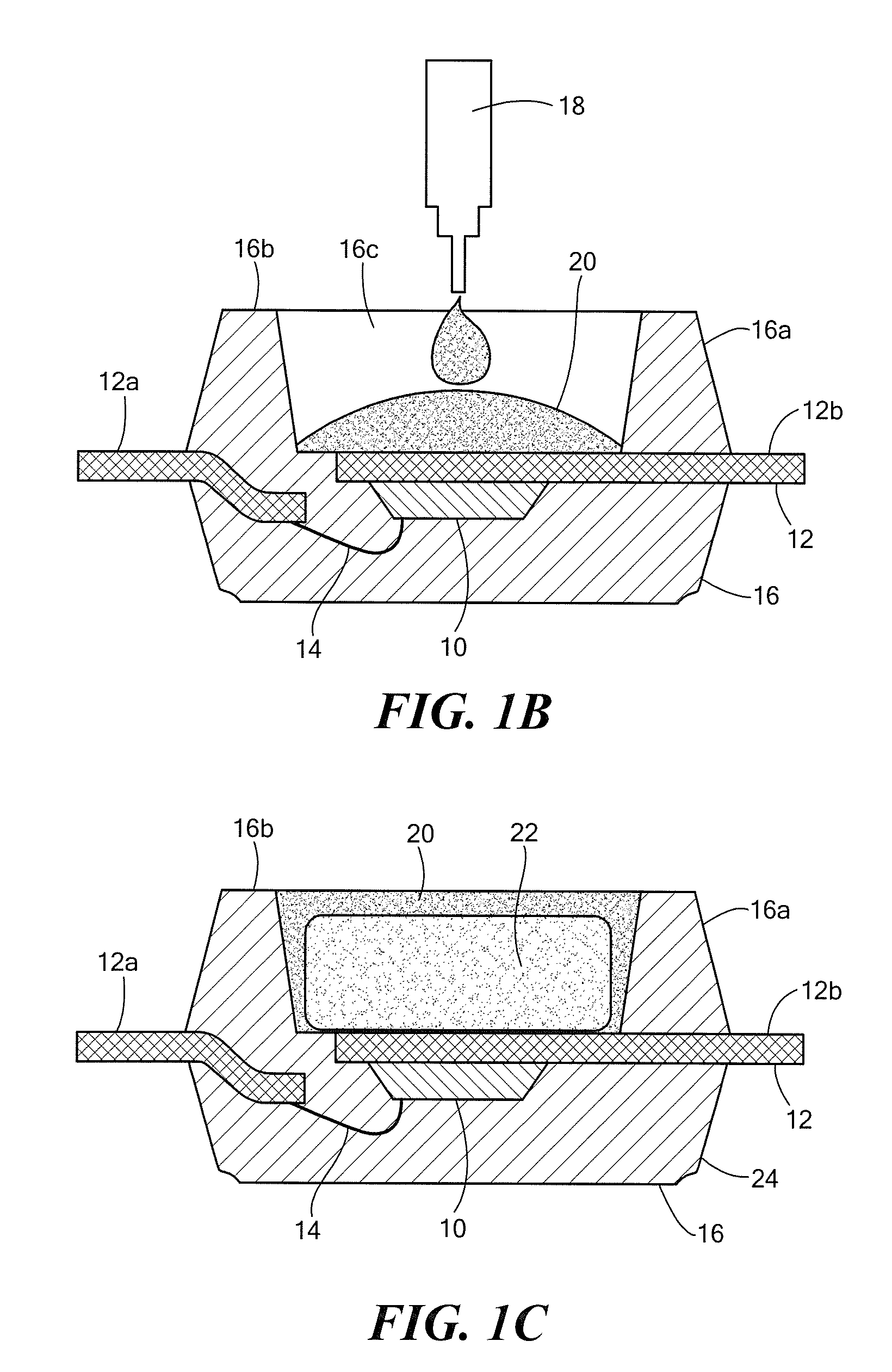
[0034]Before describing the present invention, some introductory concepts and terminology are explained. As used herein, the term “magnetic field sensor” is used to describe a circuit that includes a “magnetic field sensing element.” Magnetic field sensors are used in a variety of applications, including, but not limited to, a current sensor that senses a magnetic field generated by a current flowing in a current conductor, a magnetic switch or “proximity detector” that senses the proximity of a ferromagnetic object, a proximity detector that senses passing ferromagnetic articles, for example, magnetic domains of a ring magnet or gear teeth, and a magnetic field sensor that senses a magnetic field density of a magnetic field.

[0035]While magnetic field sensing elements are shown and described below to be Hall effect elements, in other arrangements, the magnetic field sensing elements can be, but are not limited to, Hall effect elements, magnetoresistance elements, or magnetotransisto...


PUM

PropertyMeasurementUnit
magnetic fieldaaaaaaaaaa
strengthaaaaaaaaaa
flux densityaaaaaaaaaa

Abstract

Magnetic field sensors and associated methods of manufacturing the magnetic field sensors include molded structures to encapsulate a magnetic field sensing element and an associated die attach pad of a lead frame and to also encapsulate or form a magnet or a flux concentrator.

Description

CROSS REFERENCE TO RELATED APPLICATIONS[0001]Not Applicable.STATEMENT REGARDING FEDERALLY SPONSORED RESEARCH[0002]Not Applicable.FIELD OF THE INVENTION[0003]This invention relates generally to magnetic field sensors, and, more particularly, to magnetic field sensors having a magnetic field sensing element die and magnet and also to the assembly and packaging of the magnetic field sensors.BACKGROUND OF THE INVENTION[0004]Magnetic field sensors in the form of so-called “proximity detectors” that can detect the presence of a ferromagnetic object proximate to the magnetic field sensor are known. Proximity detectors typically include a permanent magnet to generate a magnetic field and also include a magnetic field sensing element, for example, a Hall effect element, to detect changes in the strength of the magnetic field associated with the permanent magnet as a ferromagnetic object moves through the magnetic field.[0005]The output signal of a magnetic field sensing element is dependent ...

Claims


Application Information

Patent Timeline
Patent Type & Authority Applications(United States)
IPC IPC(8): G01R33/02B32B38/00
CPCG01R33/0047H01L43/12H01L43/02G01R33/02H01L2224/48091H01L2224/48247H01L2924/10156H01L2924/1815H01L2924/181H01L2924/00014H01L2924/00012H10N50/80H10N50/01
Inventor ARARAO, VIRGILSHARMA, NIRMALENGEL, RAYMOND W.GAGNON, JAYSAUBER, JOHNTAYLOR, WILLIAM P.KAM-LUM, ELSA
Owner ALLEGRO MICROSYSTEMS INC
Why Eureka
Try Eureka