Moving Object Noise Elimination Processing Device and Moving Object Noise Elimination Processing Program

a processing device and processing program technology, applied in the field of moving object noise elimination processing device and moving object noise elimination processing program, can solve the problems of insufficient monitoring from inability to detect pedestrians or obstacles in a shot image frame, and a long time is required for processing, so as to achieve the effect of eliminating moving object noise, reducing memory consumption, and increasing luminance valu

Inactive Publication Date: 2010-06-10
HOKKAIDO UNIVERSITY +1
View PDF4 Cites 57 Cited by
  • Summary
  • Abstract
  • Description
  • Claims
  • Application Information

AI Technical Summary

Benefits of technology

[0023]At least one of the above configurations uses a fixed imaging device, a memory, and a processing means that processes a shot image frame for moving object noise elimination processing. The processing means is a computer. Luminance values of corresponding pixels are compared between an image frame shot at a time before the current time and an image frame shot at the current time to eliminate pixels having higher luminance values as noises. Since an object closer to the imaging device is generally imaged brighter, a moving object on the front side has a higher luminance value than an object to be imaged on the back side. Therefore, the above configurations enable the moving object noise to be eliminated from two images, and if an image frame shot at the current time is acquired, the moving object noise may be eliminated substantially in real time by the simple luminance value comparison with an image frame already shot before that time. Therefore, the moving object noise may effectively be eliminated with a relatively simple method.
[0024]At least one of the above configurations uses a fixed imaging device, a memory, and a processing means that processes a shot image frame for moving object noise elimination processing. The processing means is a computer. The frequency distribution of luminance values of corresponding pixels is generated in a plurality of image frames at different shot times to leave the data of the highest frequency for each of the pixels and to eliminate other data as a noise. Since the moving object moves over time, the moving object does not stop at each pixel and the luminance value of the moving object varies at each pixel depending on time. On the other hand, when the object to be imaged behind the moving object is located at a fixed position or is in a substantially stationary state, each pixel has a substantially fixed luminance value. Therefore, when the object to be imaged is located at a fixed position or is in a substantially stationary state, the moving object noise may be eliminated from a plurality of images. For example, if the generation of the frequency distribution of luminance values is sequentially updated each time an image is shot, the moving object noise may be eliminated substantially in real time in accordance with the acquisition of the currently shot image frame. Therefore, the moving object noise may be effectively eliminated with a relatively simple method.
[0025]At least one of the above configurations uses two fixed imaging devices, a memory, and a processing means that processes a shot image frame for moving object noise elimination processing. The processing means is a computer. The two fixed imaging devices are arranged with a separation distance from each other such that the positions of the object to be imaged in the respective shot image frames are mismatched within arbitrarily defined pixels in the image frames. The luminance values of corresponding pixels are compared between two image frames shot at the same time by the two fixed imaging devices to eliminate pixels having higher luminance values as noises. When the two fixed imaging devices are arranged as above, even if the object to be imaged moves, the positions of the object to be imaged are matched within a range of predetermined arbitrary pixels in the two image frames shot by the two fixed imaging devices. On the other hand, in the case of a moving object closer than the object to be imaged, the positions of the moving object are not matched in the two image frames shot by the two fixed imaging devices. Since an object closer to the imaging device is generally imaged brighter, the moving object on the front side has a higher luminance value than the object to be imaged on the back side. Therefore, the above configurations enable the moving object noise to be eliminated from two images, and if two image frames are acquired from the two fixed imaging devices, the moving object noise may be eliminated substantially in real time by the simple luminance value comparison between the two image frames. Therefore, the moving object noise may be effectively eliminated with a relatively simple method.
[0026]The above configurations estimate the frequency of presence of the moving object in front of the object to be imaged based on the comparison between a total number of data of luminance values of pixels making up image frames and a number of data of luminance values eliminated as noises to output the moving object frequency. Therefore, the information related to the frequency of presence of the moving object in front of the object to be imaged may be acquired in addition to the noise elimination. For example, if the moving object is falling snow, information may be acquired for an amount of snowfall, etc., per unit time. Alternatively, if the moving object is a vehicle traveling on a road, information may be acquired for the number of passing vehicles, etc., per unit time.
[0027]A lighting device may be provided to apply light from the fixed imaging device side toward the object to be imaged. Although the noise is only increased due to the moving object in front of the object to be imaged even if the lighting device is provided in the conventional technologies, the noise due to the moving object may be eliminated regardless of the presence of the lighting.

Problems solved by technology

For example, when it is snowing heavily, even if a person exists or a vehicle travels, the person or the vehicle is hidden by snow, which is a moving object in front, and cannot be sufficiently monitored from a shot image frame.
Although a vehicle traveling at night may detect an obstacle in front with an infrared camera, an ultrasonic camera, etc., in some cases, when it is raining or snowing, the rain or snow is detected by infrared or ultrasonic imaging and a pedestrian or an obstacle cannot be sufficiently detected from a shot image frame if existing in front.
Since accumulating and averaging of images are performed in the method of Patent Document 1, a memory capacity is increased and a long time is required for the processing.
As above, according to the conventional technologies, advanced image processing is required for eliminating noises of moving objects and a large memory capacity and a long time are required for the processing.

Method used


Image

  • Moving Object Noise Elimination Processing Device and Moving Object Noise Elimination Processing Program
  • Moving Object Noise Elimination Processing Device and Moving Object Noise Elimination Processing Program
  • Moving Object Noise Elimination Processing Device and Moving Object Noise Elimination Processing Program

Examples


first example

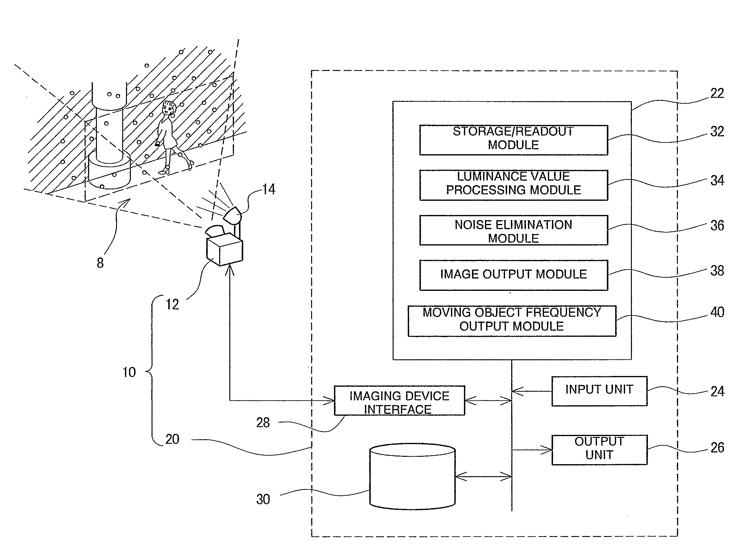
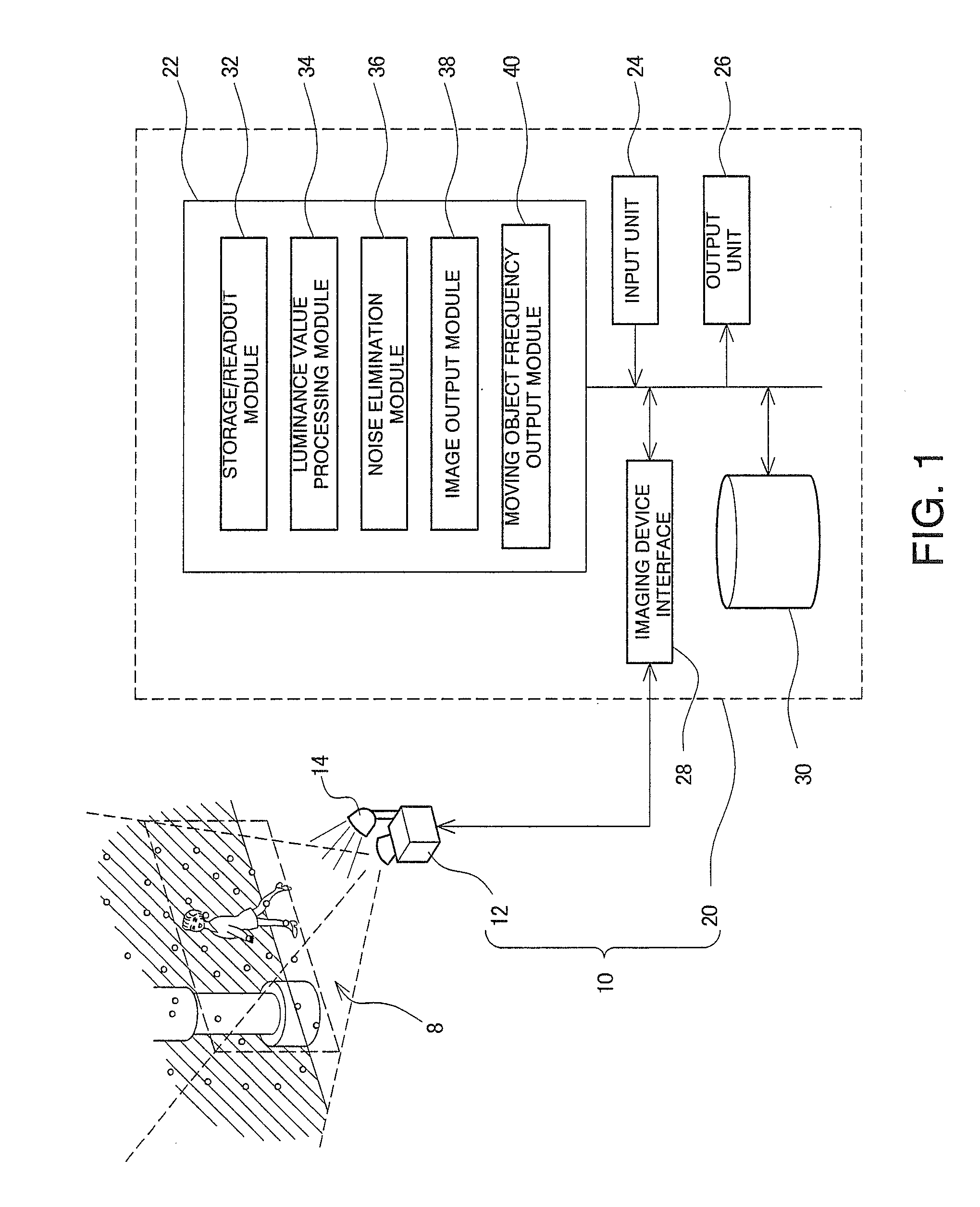
[0042]FIG. 1 is a diagram explaining a configuration of a moving object noise elimination processing device 10. The moving object noise elimination processing device 10 shown is mounted on a system monitoring outdoor situations. The outdoor situation monitoring system is made up of a camera 12 that is a fixed imaging device and a computer 20 that processes data shot by the camera 12 to output the data as monitored image frames. The moving object noise elimination processing device 10 is a portion of the outdoor situation monitoring system, is made up of the camera 12 and the computer 20 as hardware like the outdoor situation monitoring system, and is implemented as software by executing a moving object elimination processing program included in the monitoring program executed by the computer 20. FIG. 1 depicts a configuration of the moving object noise elimination processing device 10 in an extracted manner within the outdoor situation monitoring system.

[0043]FIG. 1 also depicts an ...

second example

[0071]Although the moving object noise is eliminated through comparison of the luminance values of the corresponding pixels in two image frames in the above description, a distribution of luminance values of corresponding pixels may be obtained in a plurality of image frames to eliminate the moving object noise based on the obtained luminance value frequency distribution.

[0072]Although the details of the luminance value processing module 34 are different in the CPU 22 of the computer 20 of FIG. 1 in this case, other constituent elements are the same as the description in association with FIG. 1. Therefore, a method of eliminating the moving object noise based on the frequency distribution of luminance values of pixels will be described with reference to a flowchart of FIG. 7 and FIG. 8. This method is implemented by software executed by the computer 20 of FIG. 1.

[0073]FIG. 7 is a flowchart of procedures for eliminating the moving object noise based on the frequency distribution of l...

third embodiment

[0086]The first and second examples are applicable when the object to be imaged is in the fixed state, in the substantially stationary state, or sufficiently greater than the moving objects (snow particles) in the outside situation 8. The substantially stationary state means that the movement speed of the object to be imaged in the screen is a sufficiently slower speed than the movement speed of the moving object in the screen, and the “slower speed” means that an object requires a longer time to pass by a certain pixel. In the case of falling snow, the falling speed does not fluctuate drastically and, for example, the outdoor snow falling speed is described as 400 mm / sec to 1000 mm / sec in Nonpatent Literature 1. Therefore, in an example when a ratio of outdoor speed is directly reflected on the screen, if the movement speed of the moving object is ½ to 1 / 10 of the snow falling speed out of doors, this speed may be defined as the substantially stationary state relative to the moving...


PUM


Abstract

A moving object noise elimination processing device and a moving object noise elimination processing program are provided for making it possible to effectively eliminate a noise due to a moving object in front of a photographing object with a relatively simple method. A moving object noise elimination process involves first photographing an image every predetermined sampling interval Δt and the photographed images are stored in association with time (S10, S12). Next, with respect to the currently photographed image frame data and the previously photographed image frame data, each corresponding pixel brightness value is compared (S14, S16, S18). For each pixel, the one with a higher brightness value is then eliminated as a noise and that with lower brightness value is left (S20). The brightness value in each pixel of the image frame is updated with the left brightness value in each pixel and the updated one is output (S22, S24). Further, a moving object frequency is calculated from a ratio of the total number of data to the number of data with the eliminated brightness values and the calculated one is output (S26, S28).

Description

TECHNICAL FIELD[0001]The present invention relates to a moving object noise elimination processing device and a moving object noise elimination processing program and, more particularly, to a moving object noise elimination processing device and a moving object noise elimination processing program eliminating a moving object in front that is noise for an object to be imaged from a shot image frame if a moving object exists in front.BACKGROUND ART[0002]An image frame shot by an imaging camera includes various noises along with data related to an object to be imaged. Therefore, image processing for processing an image frame is executed to extract only necessary data related to the object to be imaged or to eliminate unnecessary noises. Especially when a moving object is shot, the moving object is an object to be imaged in some cases and the moving object is a noise in other cases. Although the moving object may be extracted with a movement detecting means in the former cases, the movi...

Claims


Application Information

Patent Timeline
Patent Type & Authority Applications(United States)
IPC IPC(8): H04N5/217
CPCH04N1/4097G06T5/005G06T5/50H04N23/81
Inventor UEMURA, TOMOMASAIGUCHI, MANABU
Owner HOKKAIDO UNIVERSITY
Why Eureka
Try Eureka