
Building Control System

Active Publication Date: 2010-06-10
SCHNEIDER ELECTRIC BUILDINGS LLC
View PDF21 Cites 42 Cited by
  • Summary
  • Abstract
  • Description
  • Claims
  • Application Information

AI Technical Summary

Benefits of technology

[0003]In one embodiment, a method of operating a building control system includes installing a plurality of network devices to a communications network. Each of the plurality of network devices performs a device operation. The method also includes assigning an identifier to each of the plurality of network devices. The identifier is based on the device operation and a device location. The method further includes communicating information and coordinating operations automatically among the plurality of network devices based on the identifier.
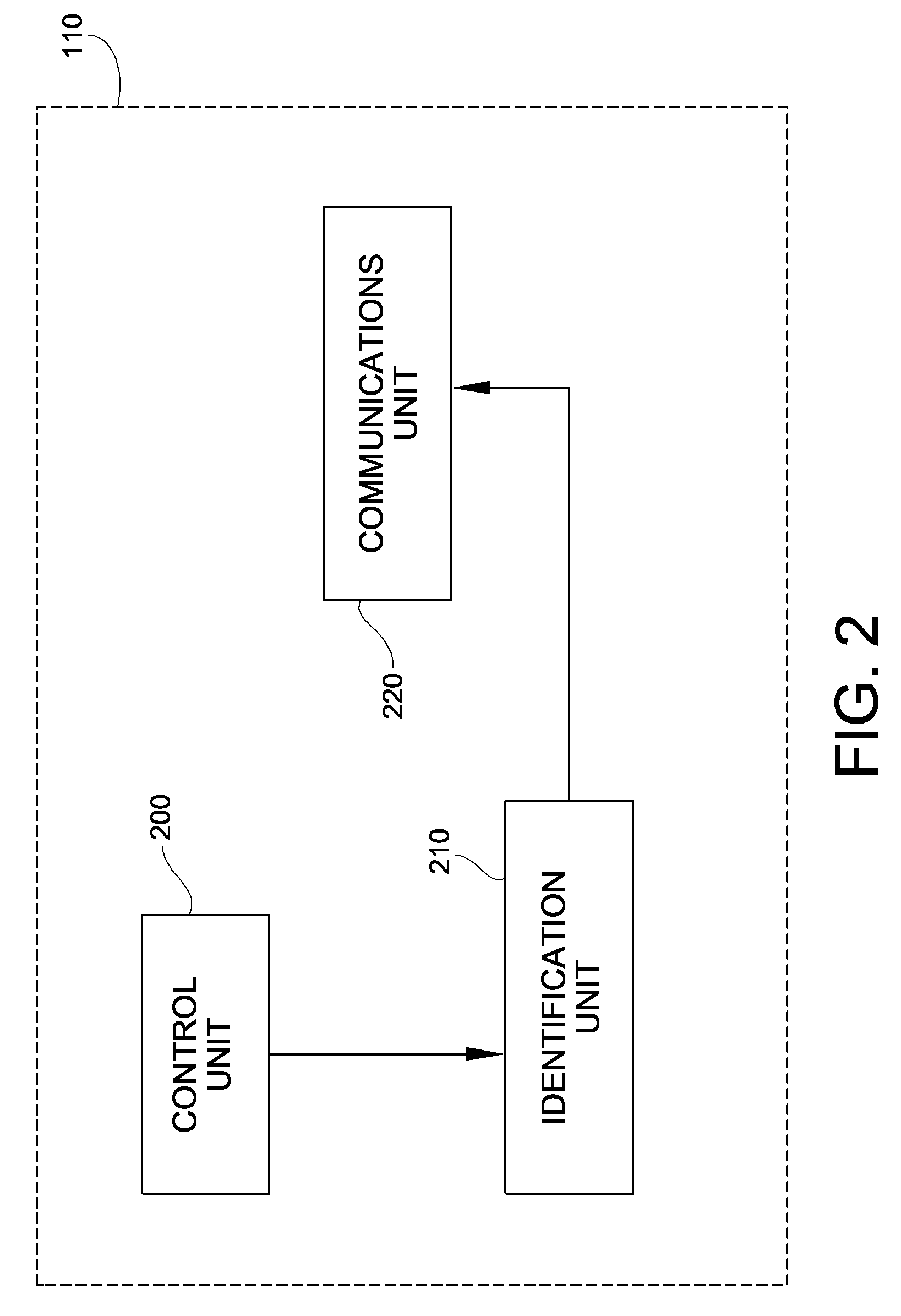
[0004]In another embodiment, a building control system includes a communications network and a plurality of network devices operably coupled to the communications network. Each of the plurality of network devices communicates information on the communications network using a data communications protocol. The building control system also includes a control unit, an identification unit, and a communications unit, all of which are operably coupled to each of the plurality of network devices. The control unit is configured to control a device operation of each of the plurality of network devices. The identification unit is configured to assign an identifier to each of the plurality of network devices. The identifier is based on the de

Problems solved by technology

This process can be expensive and time-consuming for a complex building automation network such as, for example, a commercial building network involving several network devices.

Method used


Image

  • Building Control System
  • Building Control System
  • Building Control System

Examples


Embodiment Construction

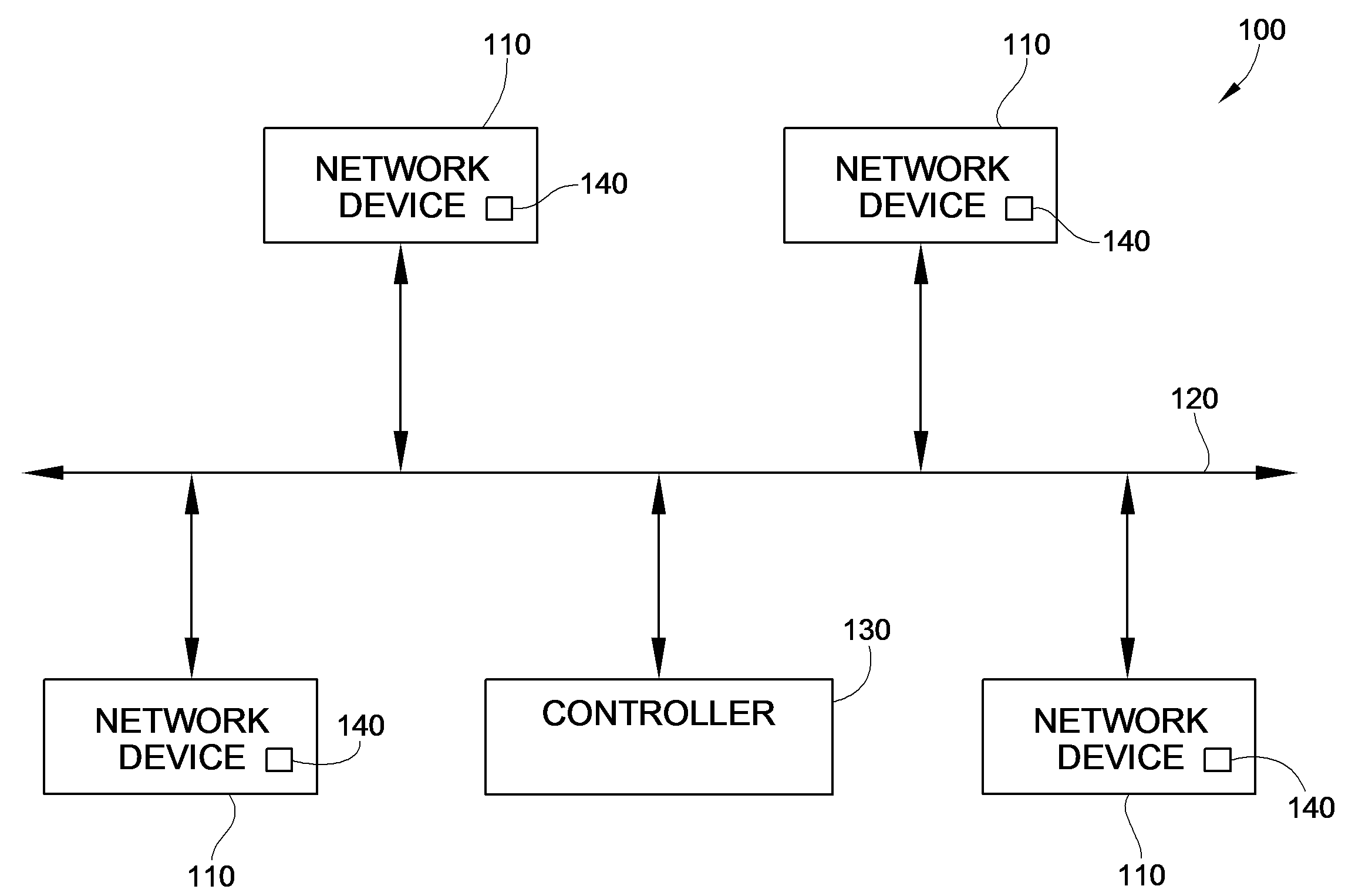
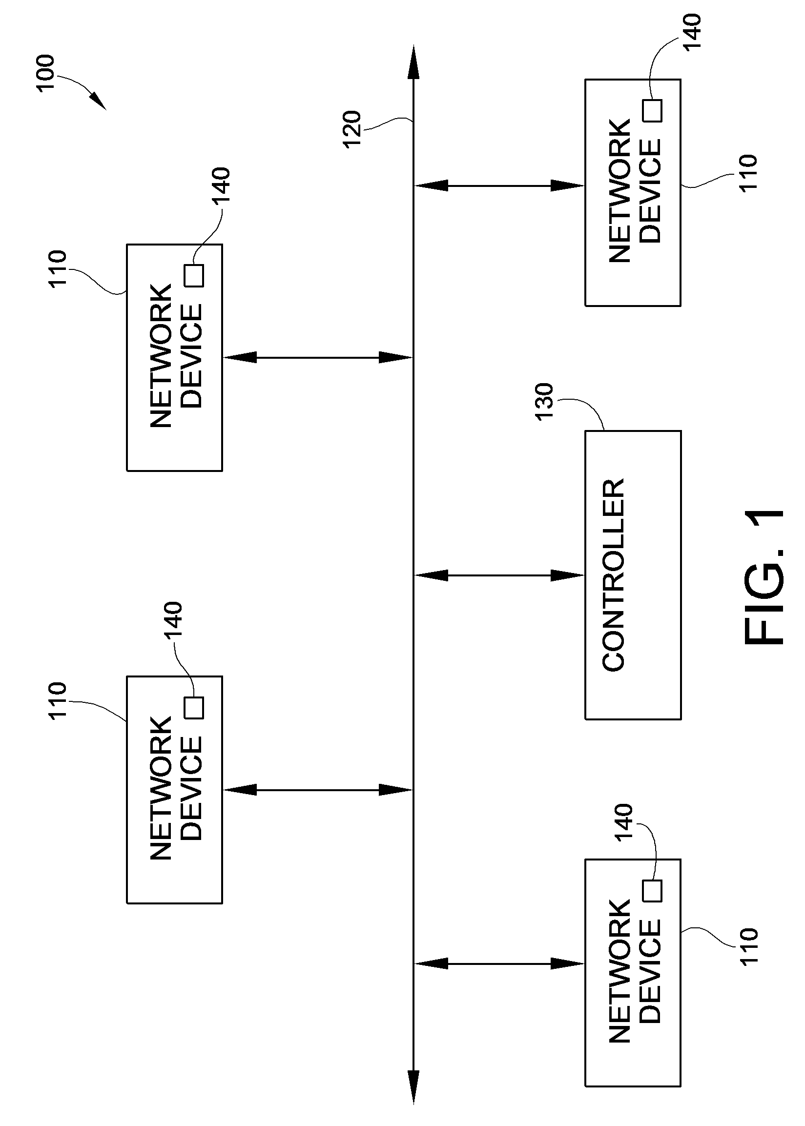
[0012]Referring to FIG. 1, a block diagram of a building control system 100 is shown. The building control system 100 may include, for example, a building automation and control network for one or more buildings in a residential, commercial, and / or industrial environment. As shown in FIG. 1, the building control system 100 includes a plurality of network devices 110 operably coupled to a communications network 120. The communications network 120 may include any type of wired and / or wireless communications media capable of transmitting data between the plurality of network devices 110 such as, for example, a twisted pair cable, an optical fiber, an AC power line, IR, RF, and the like. In one embodiment, the communications network 120 includes a network using an open-system, non-proprietary communications protocol such as, for example, the Building Automation and Controls Network (BACnet) protocol that allows for communications and interoperability among devices and subsystems develop...


PUM


Abstract

A method of operating a building control system includes installing a plurality of network devices to a communications network. Each of the plurality of network devices performs a device operation. The method also includes assigning an identifier to each of the plurality of network devices. The identifier is based on the device operation and a device location. The method further includes communicating information and coordinating operations automatically among the plurality of network devices based on the identifier.

Description

FIELD OF THE INVENTION[0001]This invention generally relates to building control systems and, more particularly, to a building control system that communicates information and coordinates operations automatically among a plurality of network devices based on an identifier.BACKGROUND OF THE INVENTION[0002]Typically, the connection or binding of network devices to a building automation system or network is accomplished with the use of an external configuration tool or other binding device. Such configuration tools may require the expertise of a trained HVAC engineer who is knowledgeable both about the layout of the building control network and the specific operations performed by each network device in the network. In addition, many network devices are manufactured by various vendors and, therefore, may have to be customized to interoperate with devices manufactured by other vendors. This process can be expensive and time-consuming for a complex building automation network such as, fo...

Claims


Application Information

Patent Timeline
IPC IPC(8): H04L12/56
CPCH04L12/2809H04L61/2038H04L41/0806H04L29/12254H04L61/5038
Inventor SWAINSTON, MICHAEL JOHNSON
Owner SCHNEIDER ELECTRIC BUILDINGS LLC
Learn More