Ct scanning device

a scanning device and scanning technology, applied in the field of medical scanning technique, can solve the problems of affecting the scanning effect, unable to meet the requirements of hospitals, and costing too much for hospitals with few patients, and achieve the effect of small space and low cos

Active Publication Date: 2010-06-10
GE MEDICAL SYST GLOBAL TECH CO LLC
View PDF11 Cites 14 Cited by
  • Summary
  • Abstract
  • Description
  • Claims
  • Application Information

AI Technical Summary

Benefits of technology

[0004]The embodiments described herein provide a CT scanning device having a closely-combi

Problems solved by technology

Such separated scanning gantry, scanning table and its support result in a large volume and thus require a large space for mounting, meanwhile, they also cost much, so they either cannot meet the requirement of hospitals that only have small spaces for mounting or

Method used


Image

  • Ct scanning device
  • Ct scanning device
  • Ct scanning device

Examples


second embodiment

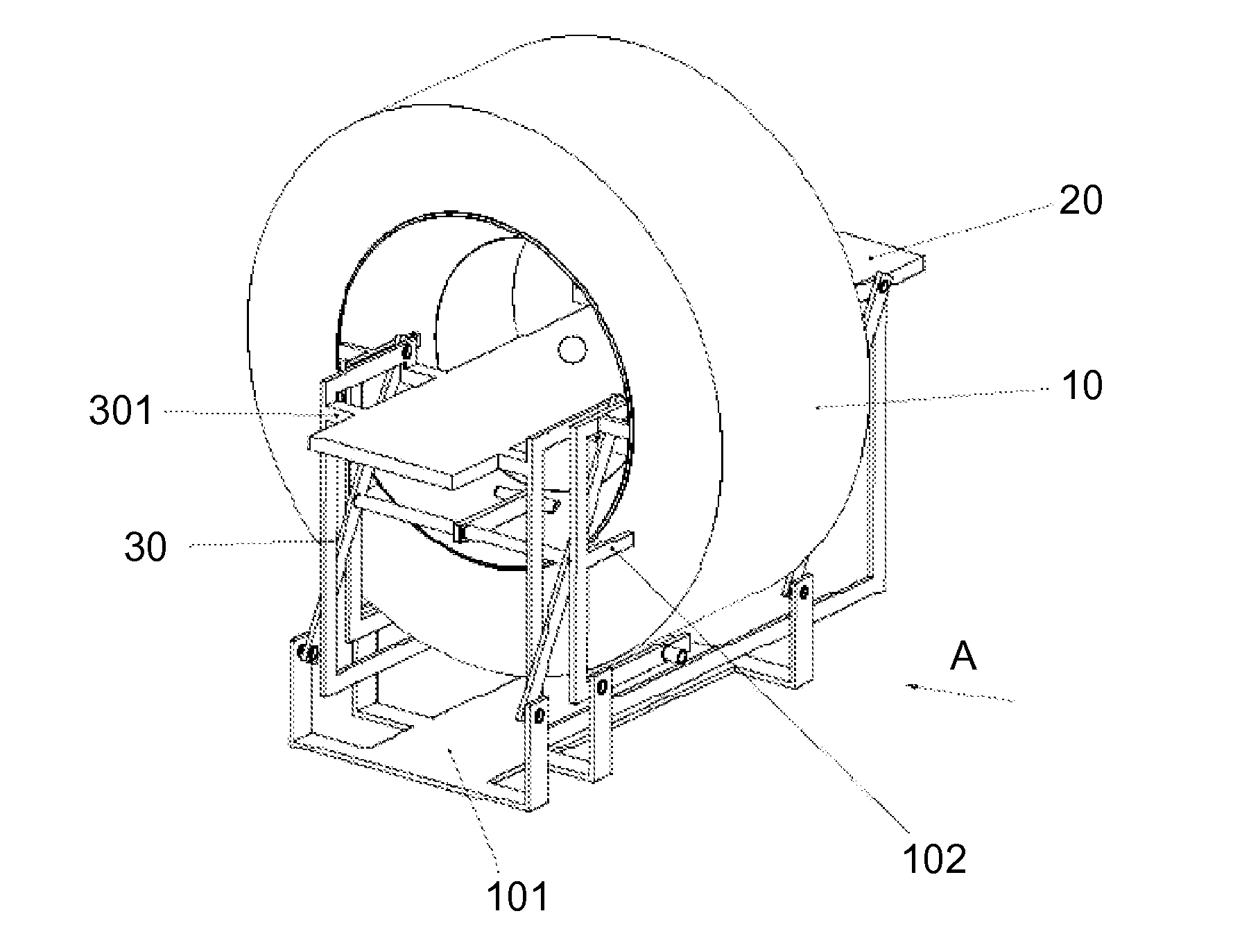
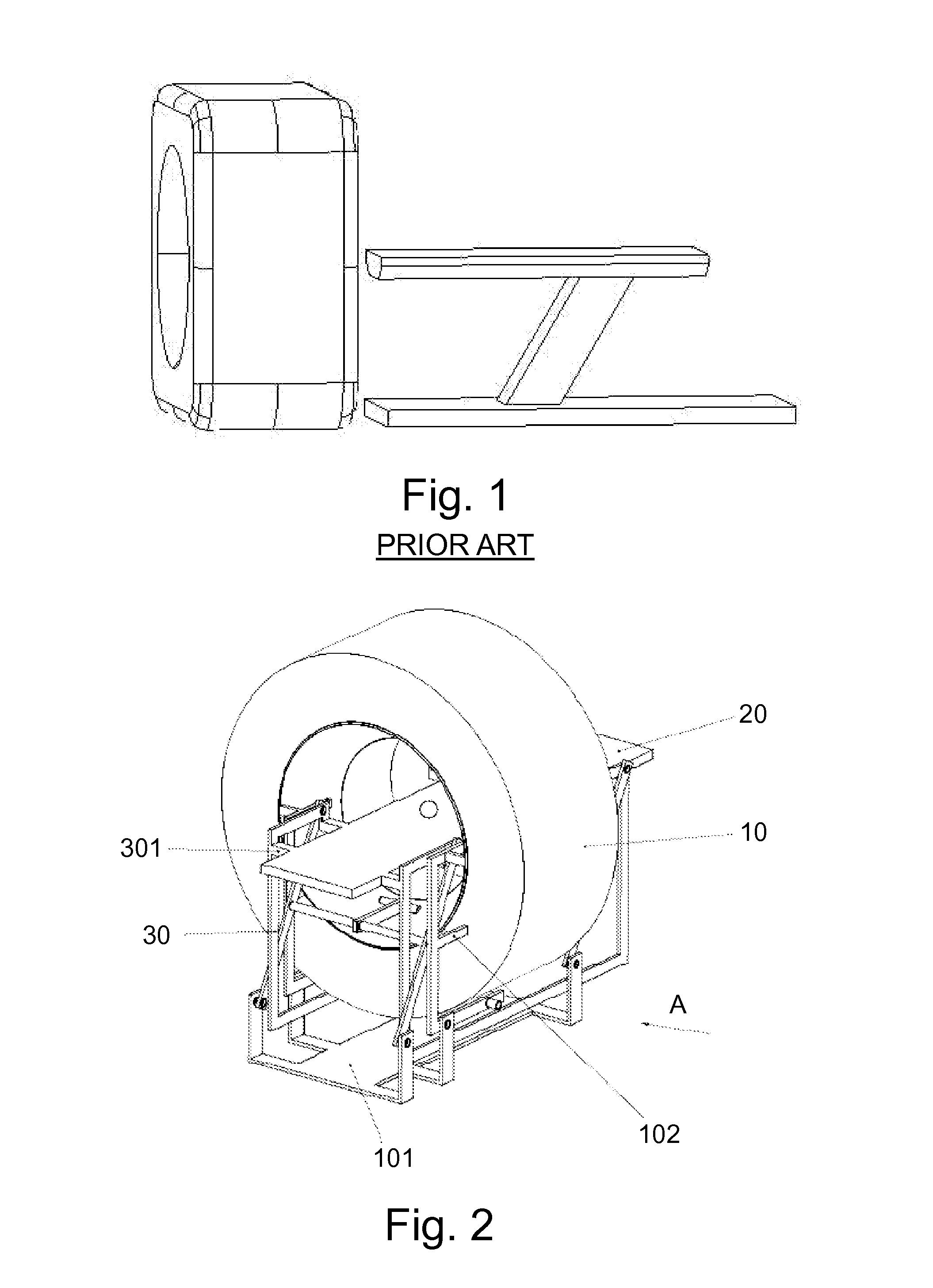
[0036]FIG. 7 is a schematic drawing of the structure of the CT scanning device of the second embodiment of the present invention. Likewise, in this embodiment, the CT scanning device also comprises a scanning gantry 10, a scanning table 20, a supporting means 30′ connected between the scanning gantry 10 and the scanning table 20 for supporting the scanning table, and a supporting base 101′ for fixing and supporting the scanning gantry 10. Driven by the table driver (not shown in the figure), said scanning table 20 can move forward and backward easily on the supporting means 30′ and can thereby come into and out of the center bore of the scanning gantry 10. Said scanning gantry 10 scans the subject and collects the scanned data.

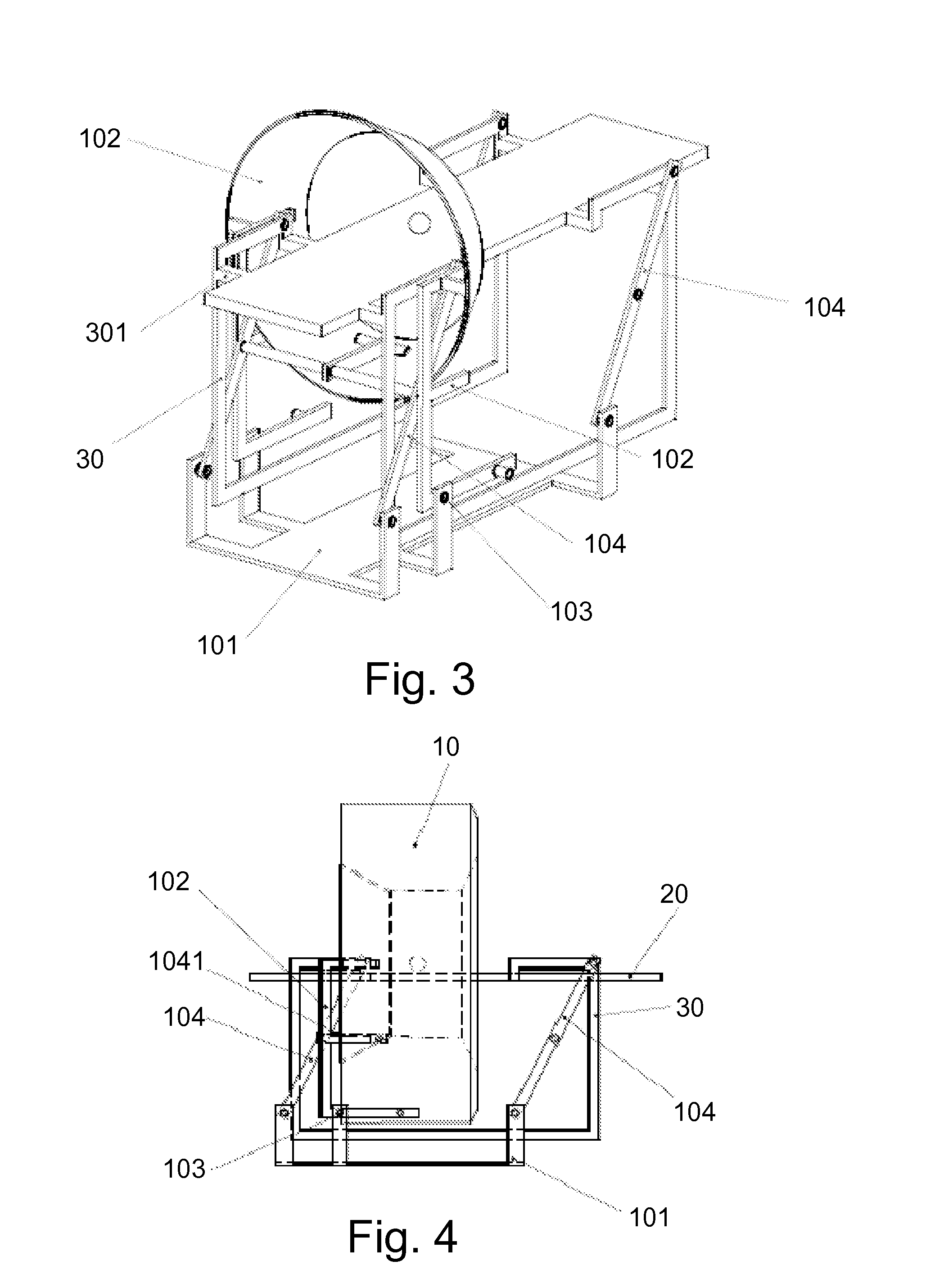
[0037]With reference to FIG. 8, said scanning gantry 10 is mounted on the supporting base 101′ through a bearing bracket 102′, and the connection point between the bearing bracket 102′ and the supporting base 101′ forms a tilting and wiggling point 103′ of the...


PUM


Abstract

A CT scanning device includes a scanning gantry, a supporting means for a scanning table, and a supporting base for fixing and supporting the scanning gantry. The scanning gantry is configured to scan a subject and to collect scanning data. The supporting means supports the scanning table, and is mounted on the supporting base and located between the scanning gantry and the supporting base.

Description

CROSS REFERENCE TO RELATED APPLICATIONS[0001]This application claims the benefit of Chinese Patent Application No. 200810181668.5 filed Dec. 4, 2008, which is hereby incorporated by reference in its entirety.BACKGROUND OF THE INVENTION[0002]The embodiments described herein relate to a medical scanning technique, and in particular to a scanning device of a computerized tomography system (hereinafter referred to as CT).[0003]The scanning gantry, scanning table and table support in the scanning device of the existing CT system are completely separated from one another, as shown in FIG. 1. Such separated scanning gantry, scanning table and its support result in a large volume and thus require a large space for mounting, meanwhile, they also cost much, so they either cannot meet the requirement of hospitals that only have small spaces for mounting or cost too much for hospitals that have few patients. In addition, the table of the existing CT scanning device is supported by a crossbeam, ...

Claims


Application Information

Patent Timeline
IPC IPC(8): H05G1/02H05G1/60
CPCA61B6/04A61B6/035
Inventor REN, JINGYIPU, YONGLI
Owner GE MEDICAL SYST GLOBAL TECH CO LLC
Why Eureka
Try Eureka