Rolling bearing device

a bearing device and rolling bearing technology, applied in the direction of shafts and bearings, mechanical equipment, transportation and packaging, etc., can solve the problems of increasing manufacturing costs and achieve the effect of satisfying both durability and manufacturing cost requirements

Active Publication Date: 2010-06-10
JTEKT CORP
View PDF8 Cites 6 Cited by
  • Summary
  • Abstract
  • Description
  • Claims
  • Application Information

AI Technical Summary

Benefits of technology

[0007]The invention provides a rolling bearing device that satisfies both durability and manufac

Problems solved by technology

However, there is a problem that manufacturing cost

Method used


Image

  • Rolling bearing device
  • Rolling bearing device
  • Rolling bearing device

Examples


Embodiment Construction

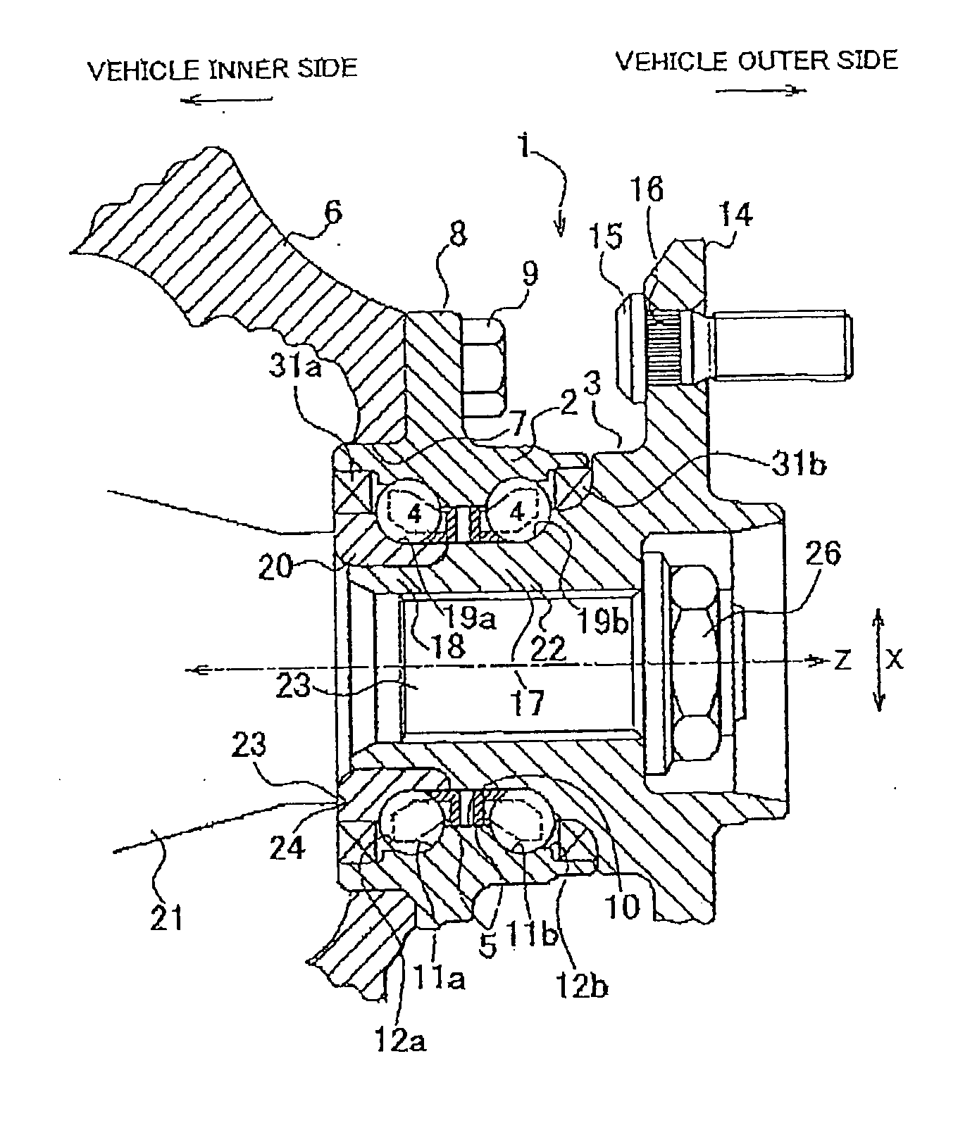
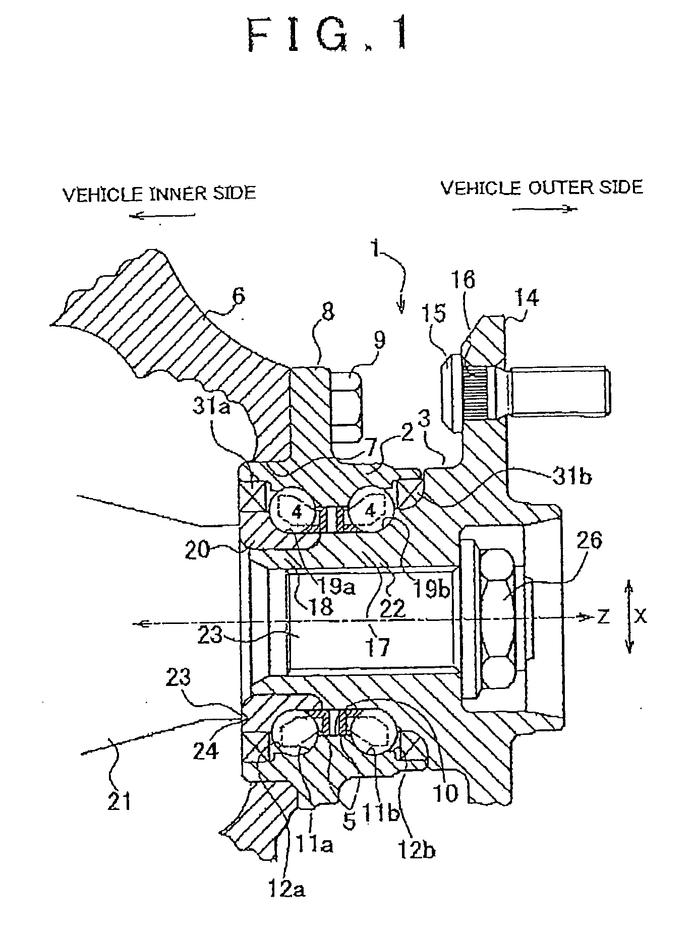
[0016]Hereinafter, an embodiment of the invention will be described with reference to a specific embodiment shown in the accompanying drawings. FIG. 1 is a cross-sectional view of an installed rolling bearing device according to the embodiment of the invention. As shown in FIG. 1, the rolling bearing device 1 (hub unit) includes an outer ring 2, an inner ring member 3 and rolling elements 4 so as to constitute a back-to-back double row angular contact ball bearing. The outer ring 2 serves as a fixed ring formed of bearing steel. The inner ring member 3 serves as a rotating ring. The rolling elements 4 formed of steel ball are interposed between the inner ring member 3 and the outer ring 2 and are arranged in double rows. A plurality of the rolling elements 4 are arranged in each row. In addition, the rolling elements 4 are retained by a retainer 5 at equiangular intervals in the circumferential direction so as to be able to freely roll between the outer ring 2 and the inner ring mem...


PUM


Abstract

A rolling bearing device includes: an outer ring that has outer ring raceway grooves formed on an inner peripheral surface of the outer ring and a counter bore portion that is provided on an outer side of the outer ring raceway grooves in an axial direction; an inner ring member that has inner ring raceway grooves formed on an outer peripheral surface of the inner ring member; and a plurality of rolling elements that are interposed between the outer ring raceway grooves and the inner ring raceway grooves so as to freely roll and that are in contact with the inner ring raceway grooves of the inner ring member and the outer ring raceway grooves of the outer ring at a predetermined contact angle. A lubricant reservoir portion that stores lubricant is formed at a portion in the outer ring raceway grooves adjacent to the counter bore portion.

Description

INCORPORATION BY REFERENCE[0001]The disclosure of Japanese Patent Applications No. 2008-309633 filed on Dec. 4, 2008 and No. 2009-247324 filed on Oct. 28, 2009 including the specifications, drawings and abstracts are incorporated herein by reference in their entiretyBACKGROUND OF THE INVENTION[0002]1. Field of the Invention[0003]The invention relates to a rolling bearing device used in a vehicle, such as an automobile.[0004]2. Description of the Related Art[0005]A rolling bearing device is used in a vehicle, such as an automobile, in order to install a tire wheel or a brake disk. A known rolling bearing device includes an inner ring that is integrally rotatably provided on an axle and that fixes a tire wheel or a brake disk and an outer ring that is located on a radially outer side of the inner ring and that is non-rotatably fixed to a vehicle body side via rolling elements (Japanese Patent Application Publication No. 2006-57686 (JP-A-2006-57686)).[0006]Then, in recent years, the se...

Claims


Application Information

Patent Timeline
IPC IPC(8): F16C33/48
CPCF16C33/6614F16C33/41F16C19/186F16C33/416F16C33/585F16C43/06F16C2326/02
Inventor MORI, TATSUKI
Owner JTEKT CORP
Why Eureka
Try Eureka