Stratified cementitious composite

a cementitious composite and cementitious technology, applied in cement production, applications, solid waste management, etc., can solve the problems of performance weaknesses associated with the boundaries between successive concrete layers and high production costs of multi-layered panels

Active Publication Date: 2010-06-10
BELLAMY LARRY ARTHUR +2
View PDF1 Cites 10 Cited by
  • Summary
  • Abstract
  • Description
  • Claims
  • Application Information

AI Technical Summary

Benefits of technology

[0006]It is an object of the present invention to provide a stratified cementitious body which overcomes or at least ameliorates some of the abovementioned disadvantages or which at least provides a useful choice.

Problems solved by technology

However, these multilayered panels are expensive to produce as they require multiple casting and curing steps.
Further, there are performance weaknesses associated with the boundaries between the successive concrete layers.

Method used


Image

  • Stratified cementitious composite
  • Stratified cementitious composite
  • Stratified cementitious composite

Examples


examples

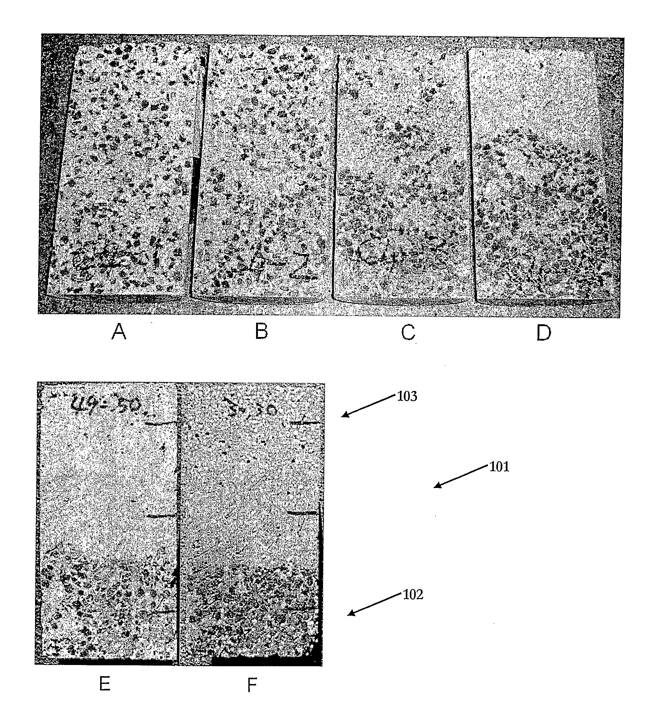
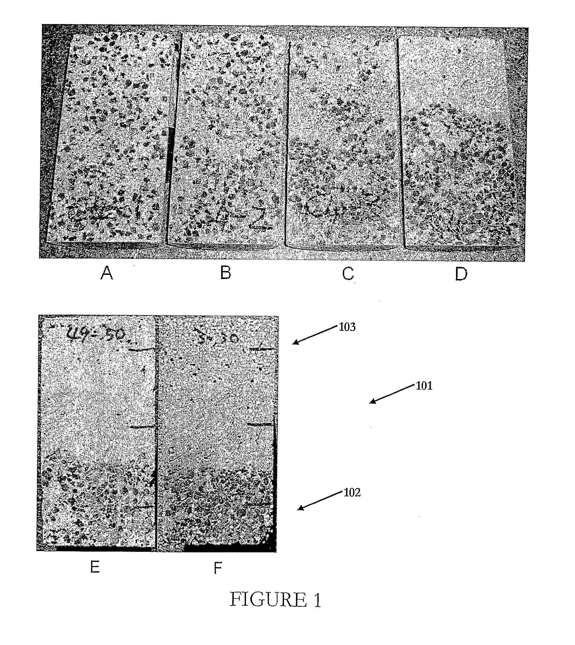
[0069]The following examples further illustrate the invention. Six concrete bodies (A, B, C, D, E and F in FIGS. 1 to 3) were prepared from concrete slurries with different rheologies according to the following steps:[0070]1. A cementitious binder, waste slag aggregate and expanded glass bead aggregate were mixed with water for 5 minutes using a rotating pan mixer to form a slurry.[0071]2. The slurry was poured into a cylindrical mould having a diameter of 100 mm and a height of 200 mm.[0072]3. The moulds were vibrated or 30 seconds at 2500 rpm.[0073]4. The slurry was left for 7 days at room temperature to set.

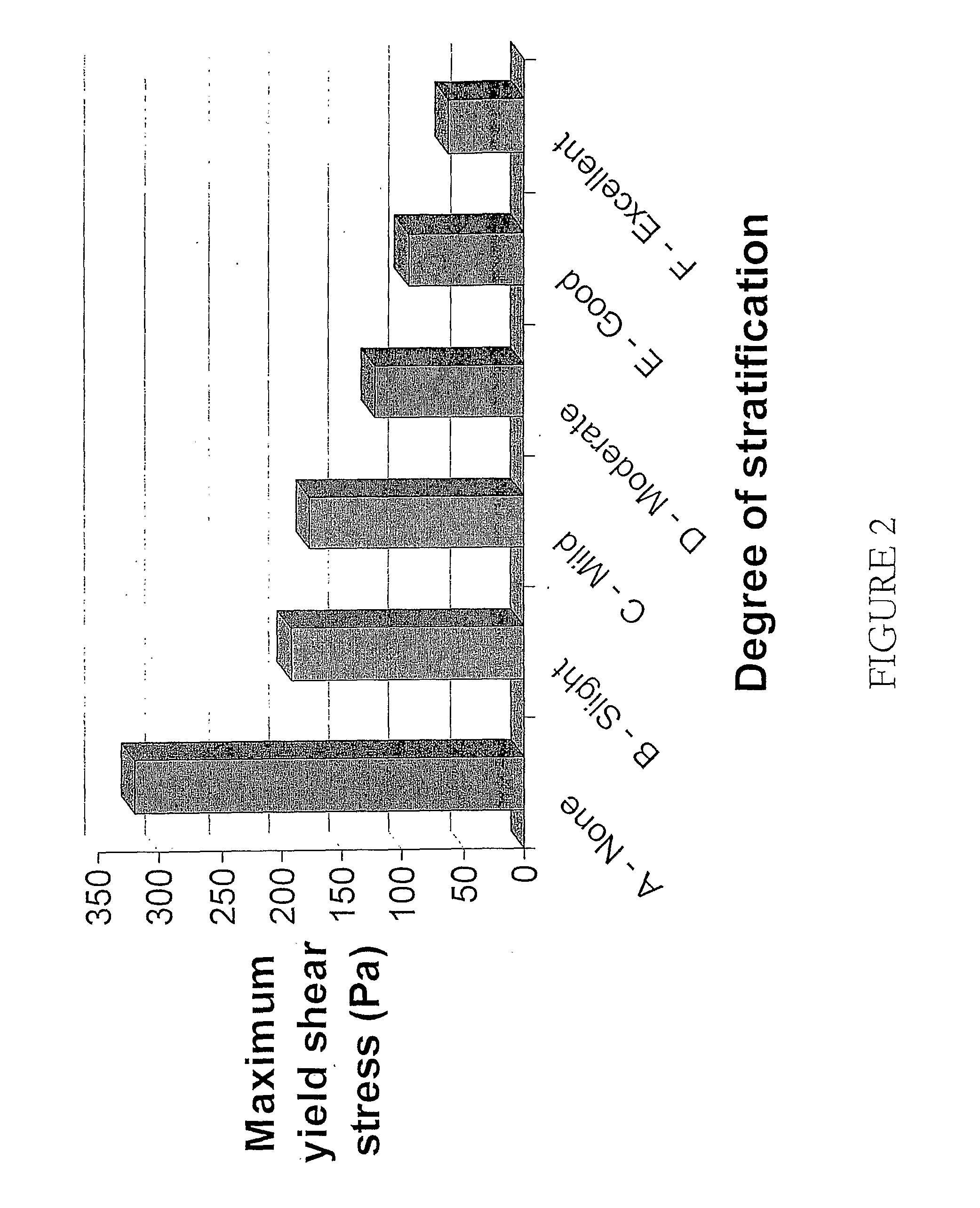
[0074]The cured concrete bodies were cut open with a diamond cutter to reveal their cross sections. The cross sections were assigned a stratification grading from ‘none’ through to ‘excellent’ based on the visual evidence of the cross section.

[0075]FIG. 1 shows the cross sections of cured Samples A through F. Sample A was completely homogeneous and exhibited no stratification....


PUM

PropertyMeasurementUnit
plastic viscosityaaaaaaaaaa
yield shear stressaaaaaaaaaa

Abstract

The present invention relates to a method for forming a stratified cementitious body comprising placing a cementitious slurry comprising a cementitious binder, to form the body in a single pour and curing the slurry to form a stratified cementitious body. The method may also comprise the steps of mixing a cementitious binder and at least one aggregate material with water to form a slurry, pouring the slurry into a mould, allowing the slurry to stratify into layers under the influence of gravitational forces and/or buoyancy forces, optionally applying vibrations to the slurry to encourage the slurry to stratify into layers, and curing the slurry to form a stratified cementitious body.

Description

FIELD OF THE INVENTION[0001]The present invention relates to stratified cementitious bodies and methods for their production and in particular, but not limited to, stratified solid concrete panels.BACKGROUND TO THE INVENTION[0002]The physical and chemical properties of cementitious bodies are varied to suit the requirements of a range of applications. For example, cementitious bodies are formed into panels for use in the construction of walls, floors, ceilings and roofs. The panels are usually made of concrete which is formed by mixing a slurry of cement and aggregate material and / or sand. The slurry is cast into a mold and cured to form a solid concrete panel.[0003]It is known that by controlling the composition of the slurry the physical properties of the solid panel can be predetermined. For example, by casting a slurry containing dense aggregate materials a panel with improved structural properties results. Alternatively by casting a slurry containing light weight aggregate mate...

Claims


Application Information

Patent Timeline
Patent Type & Authority Applications(United States)
IPC IPC(8): B32B3/26B29C39/12B29C39/00B32B9/04
CPCB28B23/0081Y10T428/2495C04B28/02C04B28/006Y10T428/24992C04B14/24C04B18/067C04B40/0067C04B14/04C04B14/16C04B14/14C04B14/18C04B14/48C04B16/06C04B14/202C04B18/141C04B16/08C04B38/106Y10T428/249973Y10T428/249974Y10T428/249971Y02P40/10Y02W30/91
Inventor BELLAMY, LARRY ARTHURMCSAVENEY, LEONARD GEORGEMACKECHNIE, JAMES RONALD
Owner BELLAMY LARRY ARTHUR
Why Eureka
Try Eureka