Flying toy having gyroscopic and gliding components

a technology of gyroscopic and gliding parts, applied in the field of aerodynamic toys, can solve the problems of affecting the flight characteristics of the flying disc itself, many such devices have experienced stalling problems, and the stalling problem is usually present, so as to achieve the effect of improving the flight characteristics

Inactive Publication Date: 2010-06-10
SCARBOROUGH GUY L
View PDF21 Cites 10 Cited by
  • Summary
  • Abstract
  • Description
  • Claims
  • Application Information

AI Technical Summary

Benefits of technology

[0009]The proposed invention presents an improvement over the prior art by providing a flying toy that includes non-rotating portions and improved flight characteristics.

Problems solved by technology

Such prior art devices have included deficiencies that have negatively affected the flight characteristics of the flying disc itself.
Many such devices have experienced stalling problems due to the additional weight of the peripheral, non-rotating items affixed to the disc.
Such stalling problems typically arise because the additional weight of the non-rotating items alters the center of gravity for the gyroscopic flying disc in such a way that detracts from the disc's ability to remain horizontally oriented during flight.
As a result, the ability of the device to fly is severely impacted by the additional, off-centered weight of the non-rotating items.
Some prior art devices have also experienced yaw problems (i.e. the disc turning or flipping over during flight) due to a combination of the additional torque and drag invariably introduced by the presence of the non-rotating items and / or the methods used to affix the items to the disc.
For example, many prior art attachment mechanisms, if placed in contact with the flying disc itself, produces frictional drag between the pin and the rotating disc, thereby reducing the spin speed of the disc.
Reduced spin speed results in diminished flight characteristics.
Similarly, many prior art attachment mechanisms produce a torque that alters the gyroscopic balance of the disc itself, thereby causing the disc to veer to one side or another and to even, in some instances, to flip over and crash into the ground.
Overall, as discussed above, many of the prior art devices while aesthetically viable, functioned poorly and exhibited flight problems that detracted from, rather than enhancing the experience of a user or an observer.

Method used


Image

  • Flying toy having gyroscopic and gliding components
  • Flying toy having gyroscopic and gliding components
  • Flying toy having gyroscopic and gliding components

Examples


first embodiment

[0179]Structure of First Embodiment Apparatus

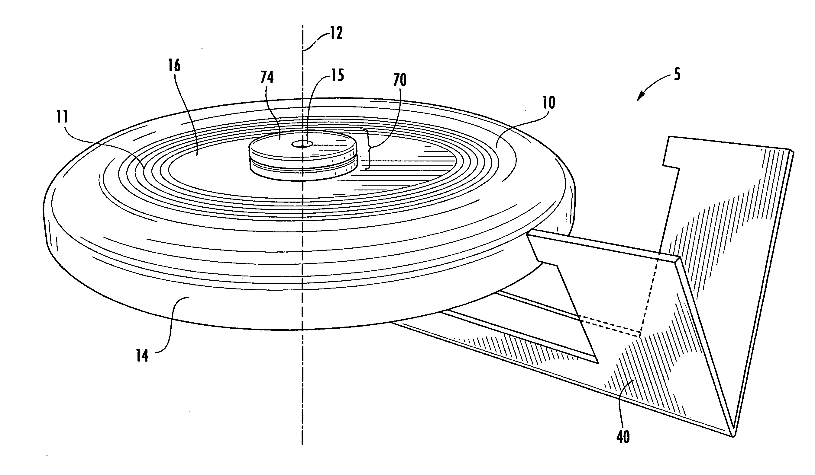
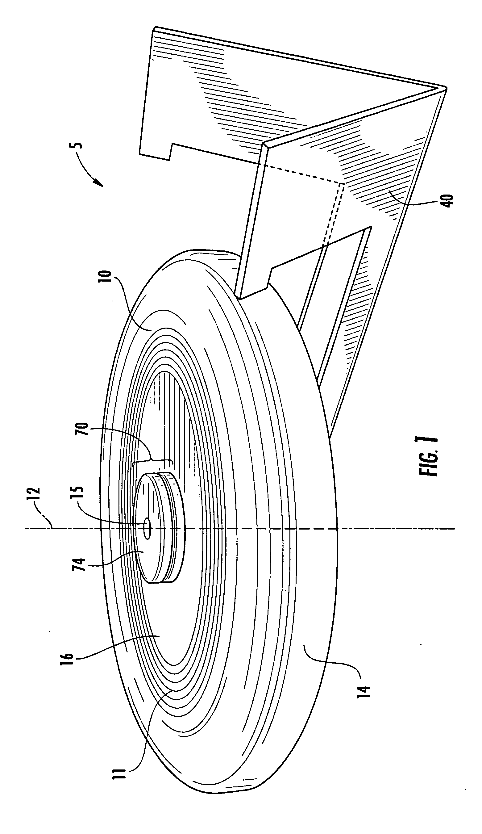
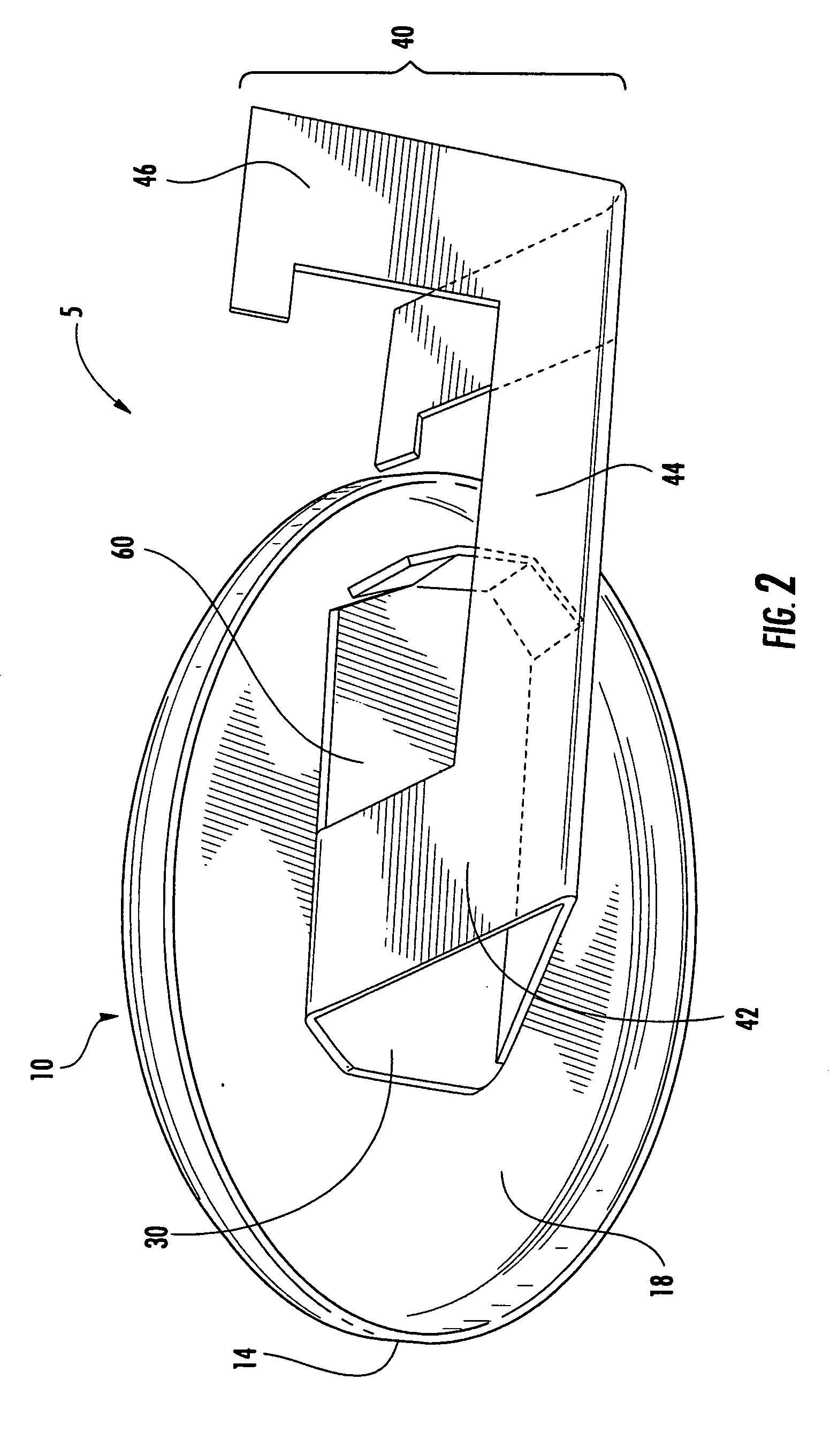
[0180]In various embodiments, as can be seen from FIGS. 1 and 2, the apparatus 5 includes a disc portion 10, a gliding body portion 20, and a rotating connection portion 70.

[0181]Generally described, the apparatus is assembled by positioning the disc portion relative to the gliding body portion as shown in FIG. 1, and completing the assembly of the rotating connection portion 70, which holds the two portions 10, 20, together.

[0182]Generally described, when the apparatus is thrown or otherwise launched in a general direction, the disc portion 10 is also given provided with spin or rotation about its central rotational axis (shown as 12 in FIG. 1), such that the gliding body portion 20“glides”, while the disc portion 10 rotates. The rotation connection portion has portions which glide, and portions which rotate, and provides a bearing connection between the two which preferably provides as little torsional drag between the two members 10, 2...

embodiment 105

Alternative Embodiment 105

[0266]FIG. 10A is a bottom view of an apparatus 105, which only includes a disc portion 110 and an aileron subassembly 160, but which does not include a fuselage subassembly. In this figure the gliding body portion 120, including the main body panel 130 and the aileron subassembly 160 (having a downwardly-directed arcuate aileron fin 164, is viewable.

[0267]A “positive pressure area”180 is shown outlined in dotted line in FIG. 10A. The airflow surrounding flying disc apparatuses has been mapped by various methods. In such maps, it has been found that the air pressure and the resulting force of that air pressure is highest in two locations relative to the disc portion 110. These locations are: (1) above and adjacent the leading edge of the disc portion 110 (i.e., toward the direction of flight), and (2) the rear of the cavity formed underneath the disc portion 110 (i.e., 180 degrees from the direction of flight). In order to have the maximum positive effect o...

embodiment 205

Alternative Embodiment 205

[0272]FIG. 11 is a bottom view of an additional embodiment apparatus 205, which includes an underside aileron subassembly 260 that is separate from the main body panel 230. The fuselage subassembly 240 is cut away for illustrative purposes. A pin 280 is also shown, which is for maintaining the angle of the aileron subassembly 260 with respect to the main body panel 230. The smaller isolated drawings shows the manner in which slots 290 in the underside aileron subassembly 260 fit around the downwardly-extending walls of the fuselage subassembly 240. The pin can fit through within the corrugated portion of the wall or be on the outside as desired.


PUM


Abstract

Provided are flying devices and methods of manufacturing and launching same, in particular flying toys or other recreational items that are designed to be thrown through the air by a user participating in any one of a variety of throwing (i.e. “catch”) games. In particular, the concept is directed toward a flying disc having rotatably attached non-rotating (a.k.a. “gliding”) portions that are attached to the disc and provide an optical illusion, wherein the user (and, similarly, an observer) does not notice the spinning of the flying disc, but instead sees a flying craft that appears to have no propulsion, yet flies. While the non-rotating portions alter the airflow associated with a typical flying disc, they do not negatively affect the flight characteristics of the disc itself. Indeed, in certain embodiments, the non-rotating portions (e.g., ailerons) have been observed to improve the flight characteristics of typical flying discs. The non-rotating portions (a.k.a. “gliding”) also provide surfaces upon which to place advertising that remains legible during flight. In this manner, the non-rotating portions of the flying device serve both a functional and an aesthetic purpose

Description

CROSS REFERENCE TO RELATED APPLICATION[0001]This application claims the full benefit and priority of pending U.S. Provisional Patent Application No. 61 / 116,509 entitled “Gyroscopic Flying Toy,” filed Nov. 20, 2008, which is hereby incorporated by reference in its entirety herein.BACKGROUND OF THE INVENTION[0002]1. Field of the Invention[0003]The general concept is directed towards aerodynamic toys that are designed to be thrown through the air by a user participating in any one of a variety of recreational throwing (i.e. “catch”) games.[0004]2. Prior Art[0005]Over the past fifty years, toys resembling discs or saucers have enjoyed great popularity as recreational items for use in throwing games and contests. In the typical embodiment, such toys have been made of a plastic material in a circular configuration with a rim portion located at its periphery. Such devices are commonly known and commercially available (i.e., for example, Frisbee brand discs, similar to that described in gre...

Claims


Application Information

Patent Timeline
Patent Type & Authority Applications(United States)
IPC IPC(8): A63H27/00
CPCA63H33/18A63H27/00
Inventor SCARBOROUGH, GUY L.
Owner SCARBOROUGH GUY L
Why Eureka
Try Eureka