Check patentability & draft patents in minutes with Patsnap Eureka AI!

Implantable support device and method of use

Inactive Publication Date: 2010-06-10
STOUT MEDICAL GROUP
View PDF27 Cites 66 Cited by
  • Summary
  • Abstract
  • Description
  • Claims
  • Application Information

AI Technical Summary

Benefits of technology

[0013]The plate can have an adjustable configuration. The plate can be used with cams. The cams can be placed within the plate. The cams can be rotated to alter the configuration of the plate. For example, rotating the cams can deform the struts of the plate to longitudinally lengthen or shorten the plate.
[0015]The surgeon can use the dynamic capabilities of the plate to properly size the plate for the patient (e.g., by lengthening, shortening, twisting, or combinations thereof to match patient anatomy). The dynamic capabilities of the plate can also reduce stress on fixation screws or pins and bone into which the plate is fixed.

Problems solved by technology

The spinal column is susceptible to many kinds of injuries, disease, and trauma.
However, the holes in plates of this type may not align optimally with acceptable attachment points on the individual vertebra.
The inability to individually tailor the plate geometry to match the optimum vertebra attachment points can reduce the effectiveness of the treatment procedure and lead to complications if a plate is mismatched during deployment.
Designs of this type typically have a larger profile than nonadjustable designs due to their increased complexity and the necessity of a slidable interface for interconnecting the multiple elements of the device.
The larger profile can result in discomfort for the patient and additional damage to surrounding tissue.
These additional locking or fixation mechanisms can further increase the bulkiness of the instrumentation.
The lack of motion in the fixator and the screw can cause increased pressure points at the interface of the screws and bone and at the interface of the screws and the fixators, even for some toggling variations of screws.
These increased stress or pressure points can cause the bone to deform (e.g., windshield wiper effect) which can loosen the screw from the bone, and / or the screw to break.

Method used


Image

  • Implantable support device and method of use
  • Implantable support device and method of use
  • Implantable support device and method of use

Examples


Embodiment Construction

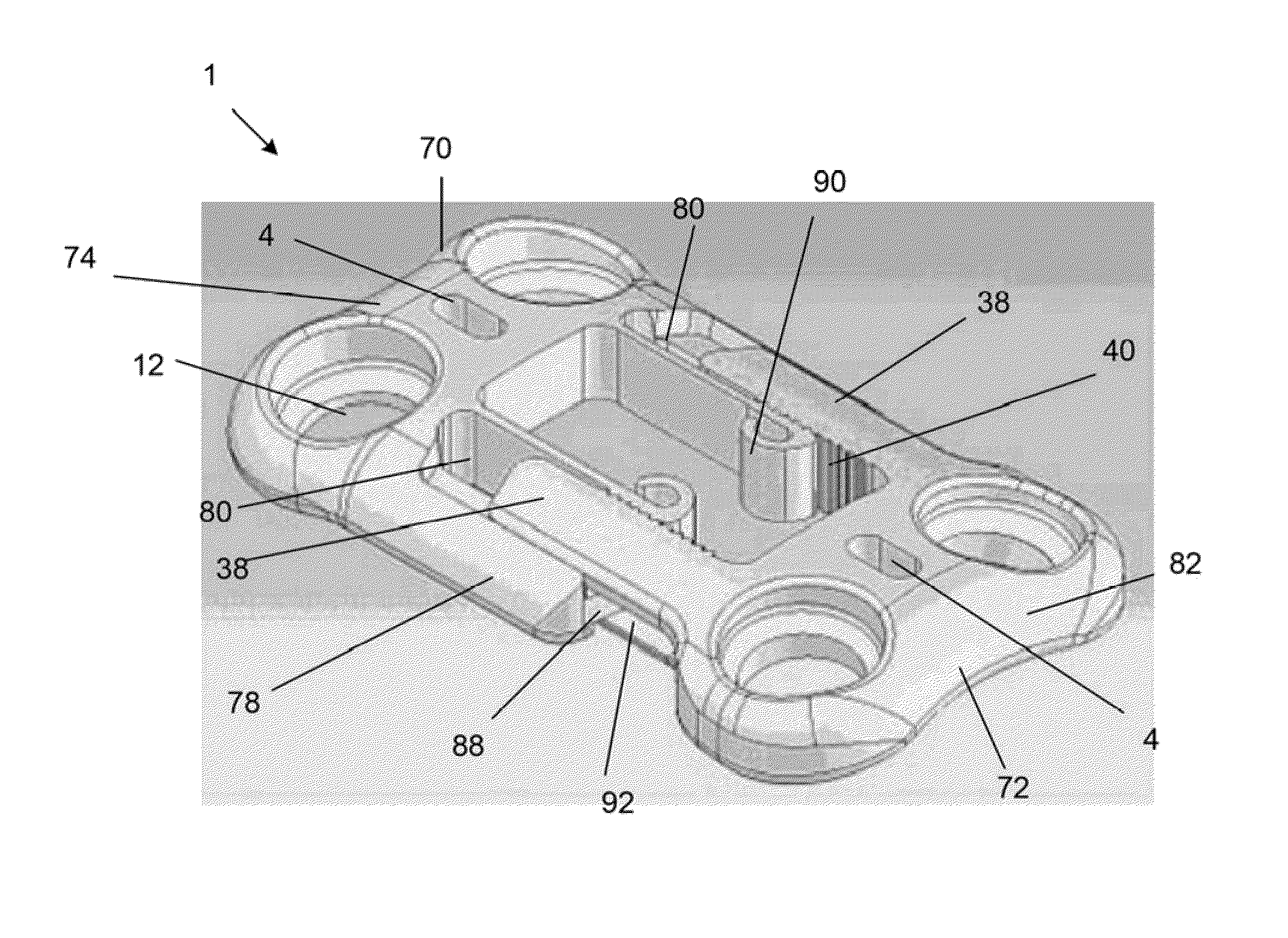
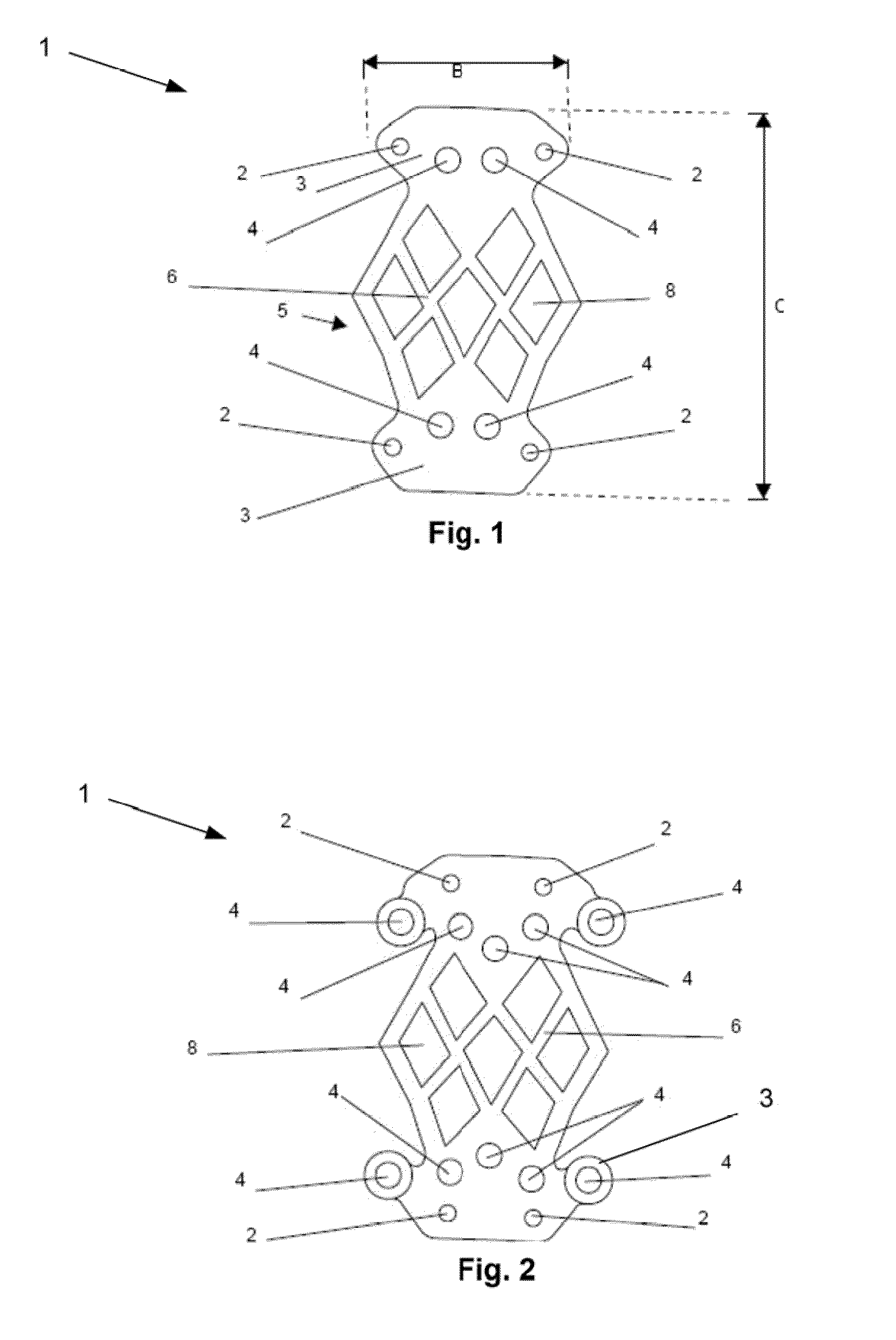
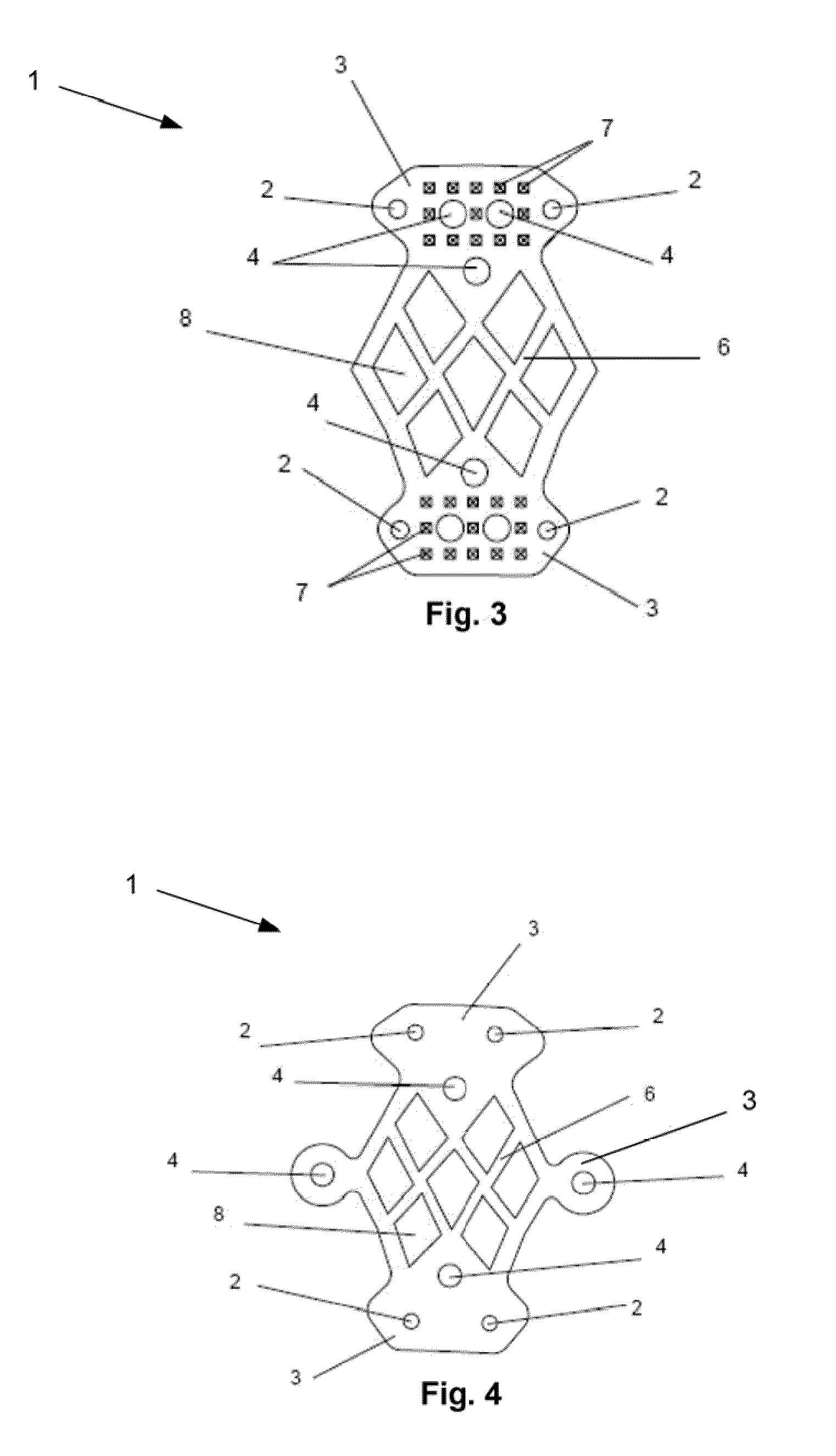
[0072]FIG. 1 illustrates an adjustable plate for spinal stabilization, fusion, and decompression. The plate 1 can be deformed or otherwise transformed by stretching, expanding or compressing. The plate 1 can be resiliently or deformably transformed, for example by lengthening, shortening, curving or twisting. The plate 1 can be transformed, for example, by a tool that can engage the plate and compress, expand, torque, or otherwise twist the plate, or combinations thereof. The plate 1 can be transformed to adjust the mounting holes to align with the target attachment sites on the bones or soft tissue of the patient. The plate 1 can be fixedly attached (e.g., at the mounting holes) to the target attachment sites on the bones. The plate 1 can be deformed or otherwise transformed before, during, or after the plate 1 is delivered to the target site, or combinations thereof. The plate 1 can be transformed in situ. For example, the plate 1 can be expanded or lengthened to create a higher d...


PUM


Abstract

A plastically-deformable spinal stabilization plate is disclosed. The spinal stabilization plate can have a number of screw-holding sockets to facilitate attachment to spinal vertebra. The spinal stabilization plate can be provided with connection points to facilitate controlled deformation or transformation of the plate by use of a deformation tool. A deformation tool is also disclosed for use in transforming the plate. The spinal stabilization plate can have a deformation area with deformation struts and apertures to facilitate a controlled deformation in a predetermined direction in response to particular deformation forces.

Description

CROSS-REFERENCE TO RELATED APPLICATIONS[0001]This application is a continuation of PCT Application No. PCT / US2008 / 077102, filed 19 Sep. 2008, which claims the benefit to U.S. Provisional Application No. 60 / 973,702, filed 19 Sep. 2007, which are both incorporated herein by reference in their entireties.BACKGROUND OF THE INVENTION[0002]1. Field of the Invention[0003]This invention relates to devices for providing support for biological tissue, for example to repair damaged vertebra, and methods of using the same.[0004]2. Description of the Related Art[0005]The spinal column is susceptible to many kinds of injuries, disease, and trauma. Some examples are herniated disks, spinal stenosis, scoliosis, fractures (e.g., compression), or a dislocation of vertebrae of the spinal column. Many of these problems may be treatable through surgical procedures. Spinal stabilization plates or assemblies of rods and clamps may be used to provide support and proper alignment to the individual vertebra ...

Claims


Application Information

Patent Timeline
IPC IPC(8): A61B17/70A61B17/88
CPCA61B17/7059A61B17/8009A61B17/8019A61B17/8869A61B17/8085A61B17/8863A61B17/8023
Inventor GREENHALGH, E. SKOTTROMANO, JOHN-PAUL
Owner STOUT MEDICAL GROUP
Features
  • R&D
  • Intellectual Property
  • Life Sciences
  • Materials
  • Tech Scout
  • Unparalleled Data Quality
  • Higher Quality Content
  • 60% Fewer Hallucinations
Learn More