Apparatus and method of spinal implant and fusion

Active Publication Date: 2010-06-10
KLEINER JEFFREY
View PDF102 Cites 95 Cited by
  • Summary
  • Abstract
  • Description
  • Claims
  • Application Information

AI Technical Summary

Benefits of technology

[0038]Another unique tool in the present disclosure is a cannula having a shape other than round (e.g., oval, pointed, square cornered, egg-shaped etc.) and having an end (e.g., the end inserted into the patient, distal from the user) that is angled and/or shaped to be ideally seated in a surgical site. Asymmetrical cannulas may allow visualization of the facet joint (DePuy has apparently described oval cannulas). An “egg-shaped” cross section may allow for the best view of the facet joint and minimizes the medial-lateral dissection that a round cannula would require.
[0039]Still other aspects of the invention are directed to cannula instruments that have a patient contacting end that is adjustable to assume a predetermined conformation. Thus, in one embodiment, material forms the tip end that comes into contact with bone, tissue, and particularly near especially nerve tissue, with such cannula end material being malleable to an extent necessary for the surgeon to mold the en

Problems solved by technology

The main risks of the anterior approach are vascular injury, injury to the superior laryngeal nerve leading to hoarseness, injury to the esophagus and spinal cord injury.
The limitations of this approach are that posterior-based pathology cannot be treated without fusion and that revision anterior surgery can be highly morbid because of damage to the vascular and neurological structures described.
Since the esophagus is directly in front of the vertebral body involved in an anterior fusion, it is particularly vulnerable to revision anterior surgery.
Unrecognized injury to the esophagus can lead to mediastinitis, which has an attendant mortality rate of 80%.
The more levels the surgeon attempts to fuse together, the greater the risk for a failure to fuse or pseudoarthrosis.
Posterior approaches suffer the same disadvantages as posterior surgery in other areas of the spine with increased morbidity associated with bleeding, infection, damage to normal tissues and unsightly scars—issues which are not substantial concerns with anterior neck operations.
Posterior cervical operations are much more painful than the anterior approach and in and of themselves necessitate longer hospital stays and longer postoperative recovery.
Oth

Method used


Image

  • Apparatus and method of spinal implant and fusion
  • Apparatus and method of spinal implant and fusion
  • Apparatus and method of spinal implant and fusion

Examples


Example

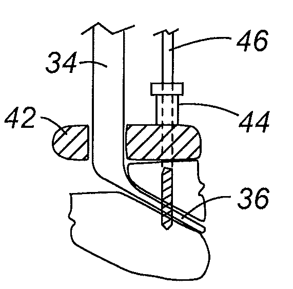
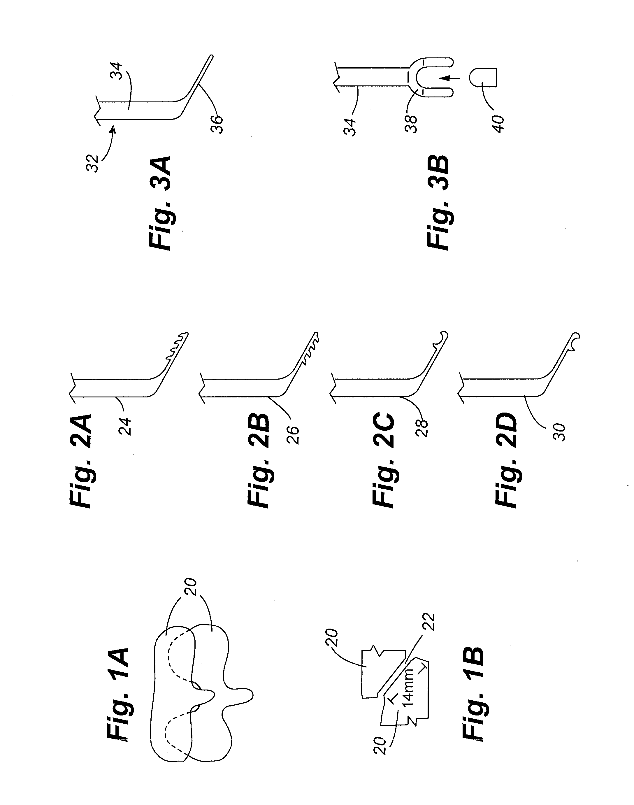
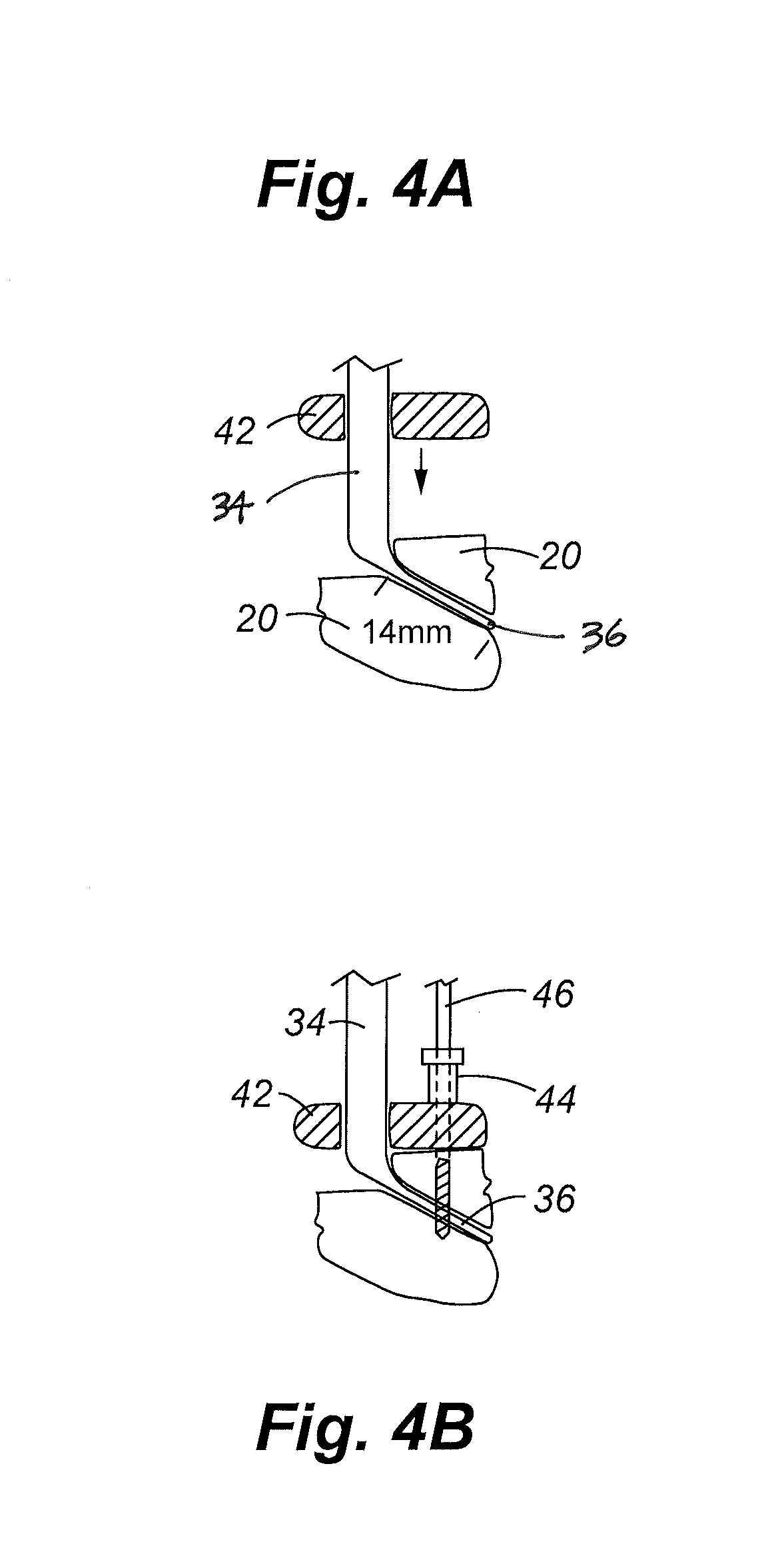
[0069]According to various embodiments described herein, the present disclosure relates to an apparatus with a handle and a forked head on the distal end of the handle, which may be used to grasp bioactive or other implant material and introduce the material to an implant site. The shaft of the apparatus is shaped so as to allow the affixation of a drill guide and drill while simultaneously holding the implant material in the implant site. Various other tools include dilators and cannula that are designed to improve accessibility and efficiency in implanting the material, as well as reduce trauma to the patient, including limiting the risk of ischemic injury due to the displacement of muscle or other tissue when accessing the implant site. In addition to these tools, fastening devices such as screws, hooks, clamps, rings, clasps, bolts and / or staples such as those described herein may also be used to secure the bioactive or other implant material to the implant site. One aspect of t...


PUM


Abstract

An apparatus and method of performing a minimally invasive posterior spine fusion. More specifically an apparatus with a handle and a forked head on the distal end of the handle is used to grasp implant material and introduce the material to an implant site. The shaft of the apparatus is shaped so as to allow the affixation of a drill guide and drill while simultaneously holding the implant material in the implant site. After removal of the boring tools and assembly of the fusing element, the apparatus can be selectively removed from the implant site. A method of achieving facet joint fusion with near simultaneous fixation is also disclosed.

Description

CROSS REFERENCE TO RELATED APPLICATIONS[0001]This application claims the benefit of U.S. Provisional Patent Application No. 61 / 120,260, filed on Dec. 5, 2008, and U.S. Provisional Patent Application No. 61 / 186,683, filed on Jun. 12, 2009, the entire disclosures of which are incorporated by reference herein in their entireties.FIELD OF THE INVENTION[0002]This disclosure relates to orthopedic surgery, and more specifically to apparatus and methods for placing an implant into a patient, for example, to promote an intervertebral fusion.BACKGROUND OF THE INVENTION[0003]Individuals who suffer degenerative disc disease, natural spine deformations, a herniated disc, spine injuries or other spine disorders may require surgery on the affected region to relieve the individual from pain and prevent further injury to the spine and nerves. Spinal surgery may involve removal of damaged joint tissue, insertion of a tissue implant and / or fixation of two or more adjacent vertebral bodies. The surgica...

Claims


Application Information

Patent Timeline
IPC IPC(8): A61B17/88A61B17/56A61B17/08A61M25/00
CPCA61B17/025A61B17/0642A61B17/1659A61B17/1671A61B17/3421A61B17/7064A61B17/7076A61B2017/0256A61B2017/3433A61B2017/922A61B17/7082A61B17/846A61B17/864A61B2017/00004A61L24/046A61L24/12A61L2400/06A61F2/4405A61B17/1757A61F2002/30622A61F2002/30754A61F2220/0016A61F2/30724A61F2/4455A61F2/4611A61L27/54
Inventor KLEINER, JEFFREY
Owner KLEINER JEFFREY
Why Eureka
Try Eureka