Air Beam with Stiffening Members and Air Beam Structure

a technology of air beams and stiffening members, applied in the direction of extraordinary structures, building components, shaping building parts, etc., can solve the problems of not being able to predict the buckling conditions, and the difficulty of applying conventional finite element software and methods, so as to optimize the position of cables

Inactive Publication Date: 2010-06-17
LUKASIEWICZ STANISLAW +1
View PDF14 Cites 21 Cited by
  • Summary
  • Abstract
  • Description
  • Claims
  • Application Information

AI Technical Summary

Benefits of technology

[0015]The positions of the attachment of the cables to the pneumatic columns may be obtained by analysis through the method of the FSCSA software. Using the FSCSA method it is possible to optimize the po

Problems solved by technology

The pneumatic column is a very flexible member of the system and it is not possible to predict its buckling conditions using method and software that are commercially available on the market.
Parti

Method used


Image

  • Air Beam with Stiffening Members and Air Beam Structure
  • Air Beam with Stiffening Members and Air Beam Structure
  • Air Beam with Stiffening Members and Air Beam Structure

Examples


Embodiment Construction

[0051]Generally, the present invention provides a method and apparatus for designing and providing an air beam structure.

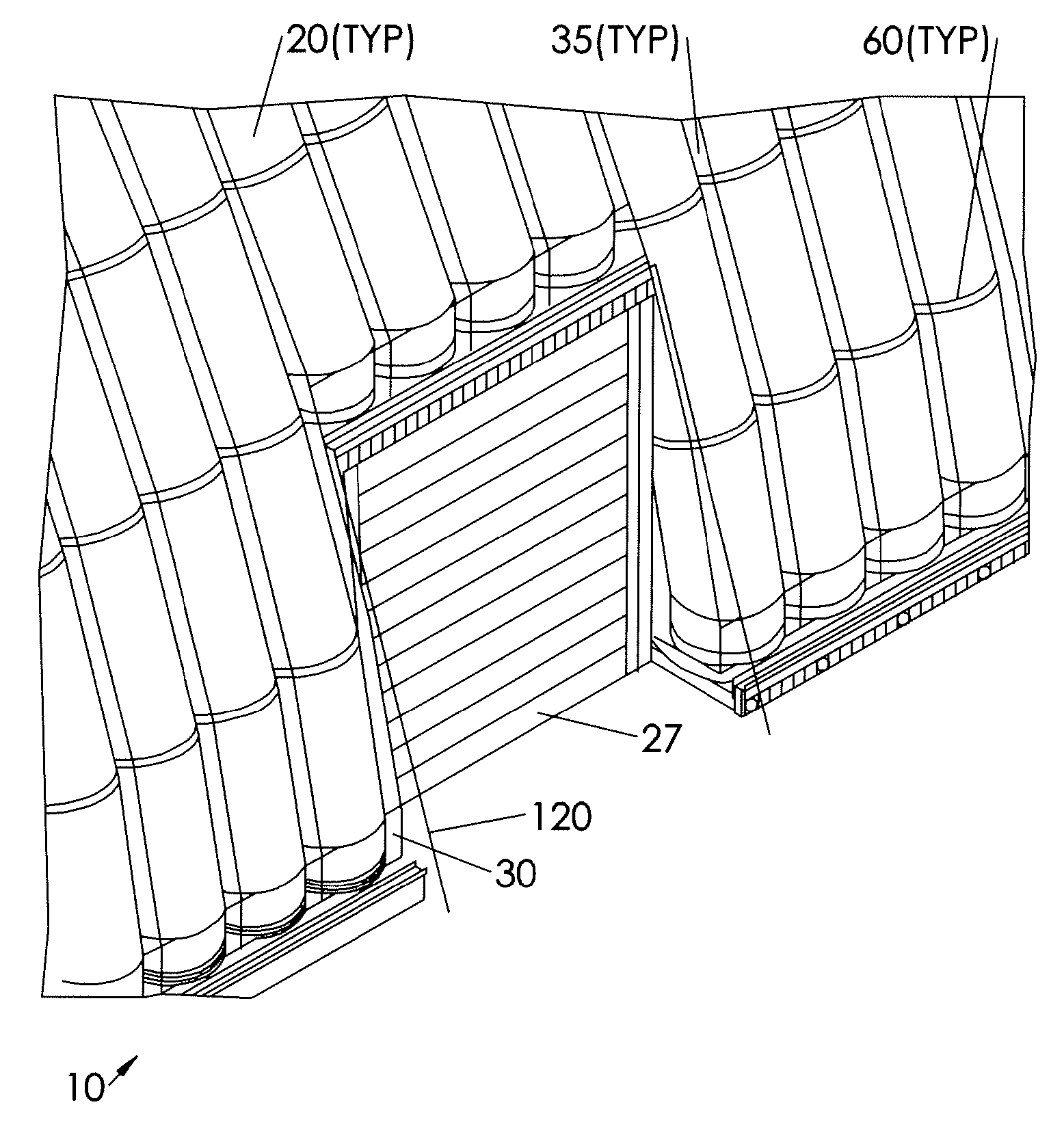
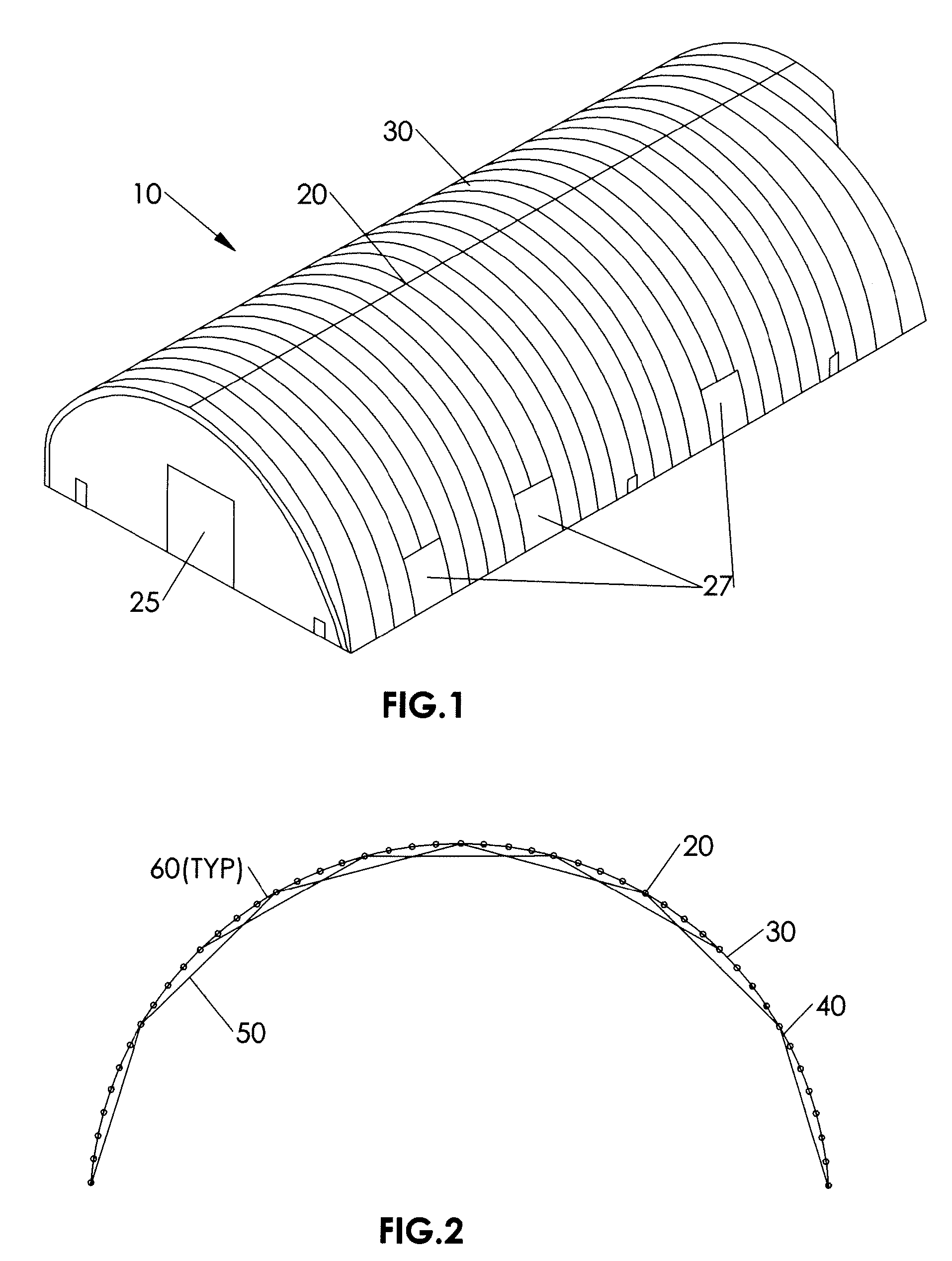
[0052]Referring to FIGS. 1 and 2, a structure 10 of the present invention is assembled from a plurality of structural members 20 covered by a flexible membrane 30. The structural member 20 includes an elongate pneumatic tubular column 40 formed into an arch shaped air beam. A plurality of stiffening members in the form of cables 50 are connected with the tubular column 40 by connectors 60. As shown, the cables 50 generally traverse the inside of the tubular column 40 to increase its resistance to bending, buckling, collapse or a combination of bending, buckling, or collapse from exterior loads such as wind, snow, sand, ice etc.

[0053]The structure 10 may include one or more end wall doors 25 and / or side wall doors 27.

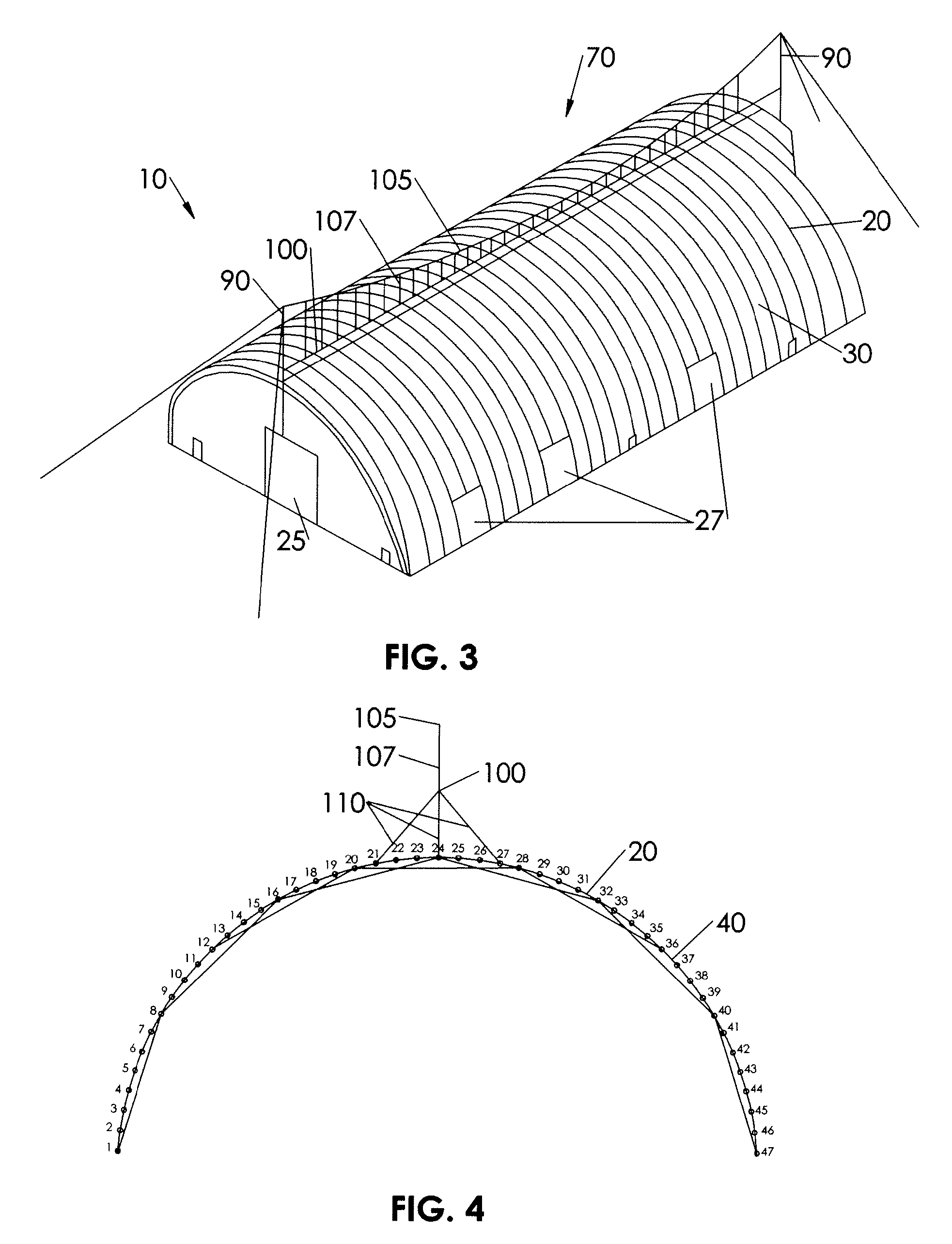
[0054]The positions of the connectors 60 on the columns 40 are defined by means of the FSCSA method for each case. A preferred design of the attachmen...


PUM


Abstract

An air beam structural member having an elongate pneumatic tubular column, a plurality of stiffening members, and means for connecting the tubular column and the stiffening members. An inflatable shelter includes pneumatic tubular columns (arches) covered on both sides by flexible membranes. The columns are placed side by side to create a wall and enclosure of the space. The pneumatic columns are pressurized and keep their shape by means of a set of cables reinforcing them in the plane of the columns. The structure may be supported by an external support structure.

Description

CROSS REFERENCE TO RELATED APPLICATIONS[0001]This application claims the benefit of priority of U.S. Provisional Patent Application No. 61 / 094,710 filed Sep. 5, 2008, which is incorporated herein by reference in its entirety.FIELD OF THE INVENTION[0002]The present invention relates generally to air supported structures. More particularly, the present invention relates to air supported structures resistant to high static or dynamic load or both.BACKGROUND OF THE INVENTION[0003]There have historically been a variety of air supported structures. That is, structures which are internally pressurized. U.S. Pat. No. 3,159,165 to Cohen et al., for example, teaches a shelter or enclosure relying on pressurized air for support. As such structures require a constant air pressure to maintain the structure, a constant supply of pressurized air and a sealed entry / exit to reduce air loss.[0004]Another approach is to form an inflatable structural member, which are combined and covered to form a str...

Claims


Application Information

Patent Timeline
IPC IPC(8): E04H15/20E04B1/343E04B1/35
CPCE04H15/18E04H2015/201E04H15/20
Inventor LUKASIEWICZ, STANISLAWWARNER, HAROLD
Owner LUKASIEWICZ STANISLAW
Why Eureka
Try Eureka