Head cover of an internal combustion engine

Active Publication Date: 2010-06-17
HONDA MOTOR CO LTD +1
View PDF9 Cites 14 Cited by
  • Summary
  • Abstract
  • Description
  • Claims
  • Application Information

AI Technical Summary

Benefits of technology

[0006]An object to be achieved by the present invention is to provide a simple modification of the head cover structure that can cope with the design change and volume increase of the intake collection chamber of the engine intake system disposed above the head cover, while ensuring a sufficient volume of the breather chamber without deteriorating the NVH performance.
[0013]In the head cover of an internal combustion engine according to the present invention, because the part of the ceiling wall that opposes the intake collection chamber is constituted by a concave ceiling wall that defines a concave surface facing the intake collection chamber, it is possible to reduce the height of the head cover so that the head cover does not interfere with the intake collection chamber, while achieving a necessary volume of the breather chamber. Further, because the concave ceiling wall is formed with a recessed groove that further recedes toward the inner side of the head cover, it is possible to improve the panel rigidity of the concave ceiling wall and prevent deterioration of NVH performance.

Problems solved by technology

However, the size increase of the breather chamber of the head cover in the lateral direction can lead to a ceiling wall of the head cover having a large flat surface, and this can reduce a panel rigidity of the ceiling wall, which in turn makes the ceiling wall easier to resonate with vibrations generated by the valve mechanism and the like on the engine main body side, and thus deteriorates the performance regarding the vibration and noise phenomena (NVH performance).

Method used


Image

  • Head cover of an internal combustion engine
  • Head cover of an internal combustion engine
  • Head cover of an internal combustion engine

Examples


Embodiment Construction

[0020]Now, a preferred embodiment of a head cover according to the present invention will be described hereinafter with reference to FIGS. 1-5.

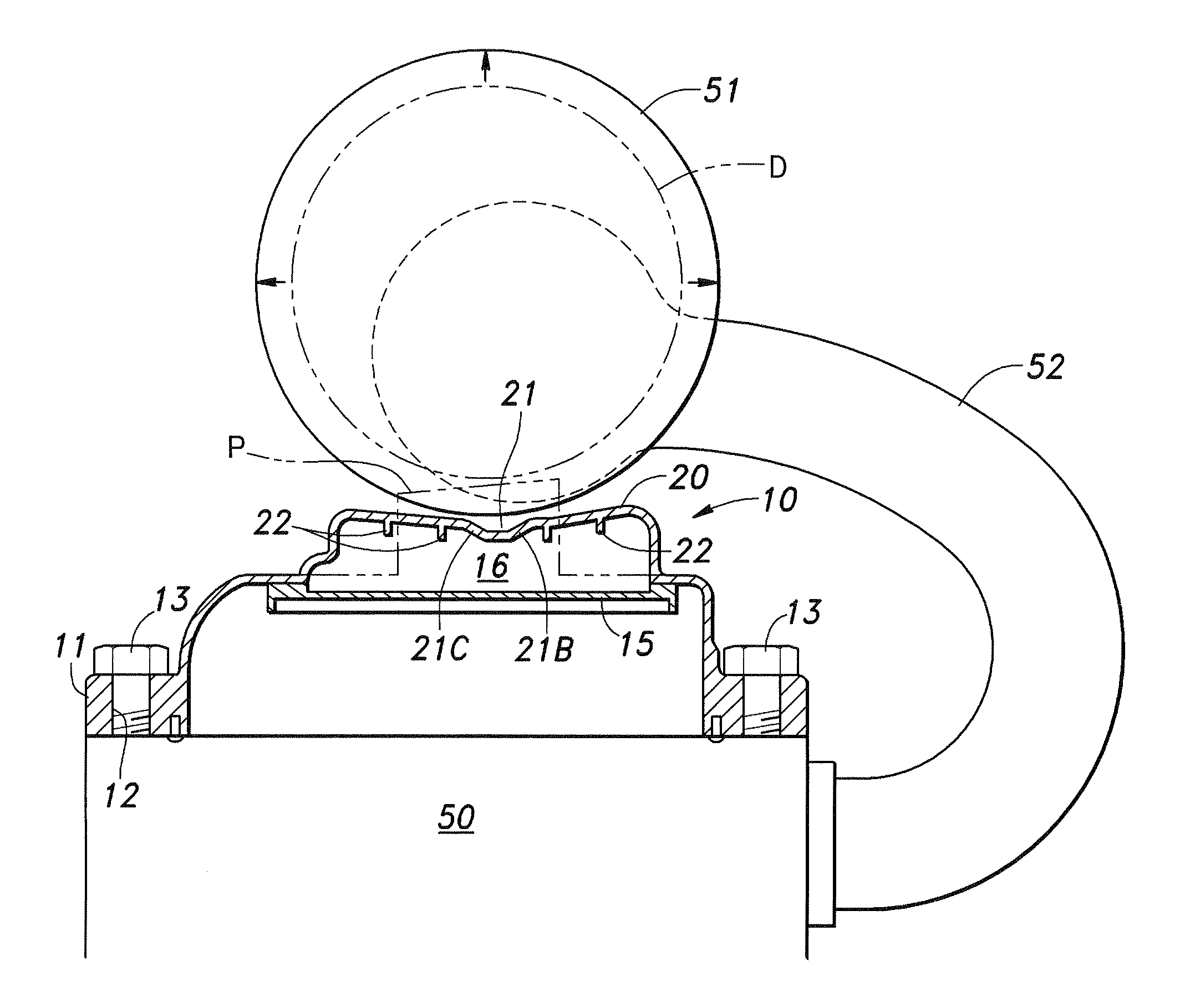
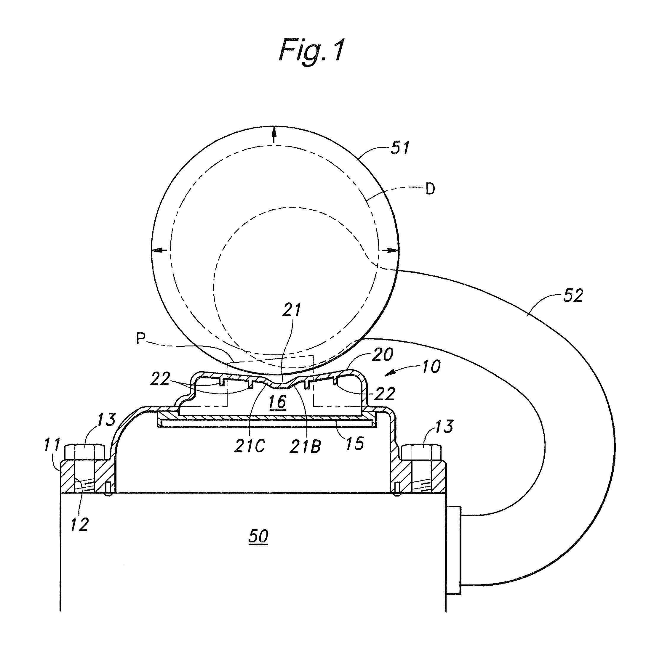
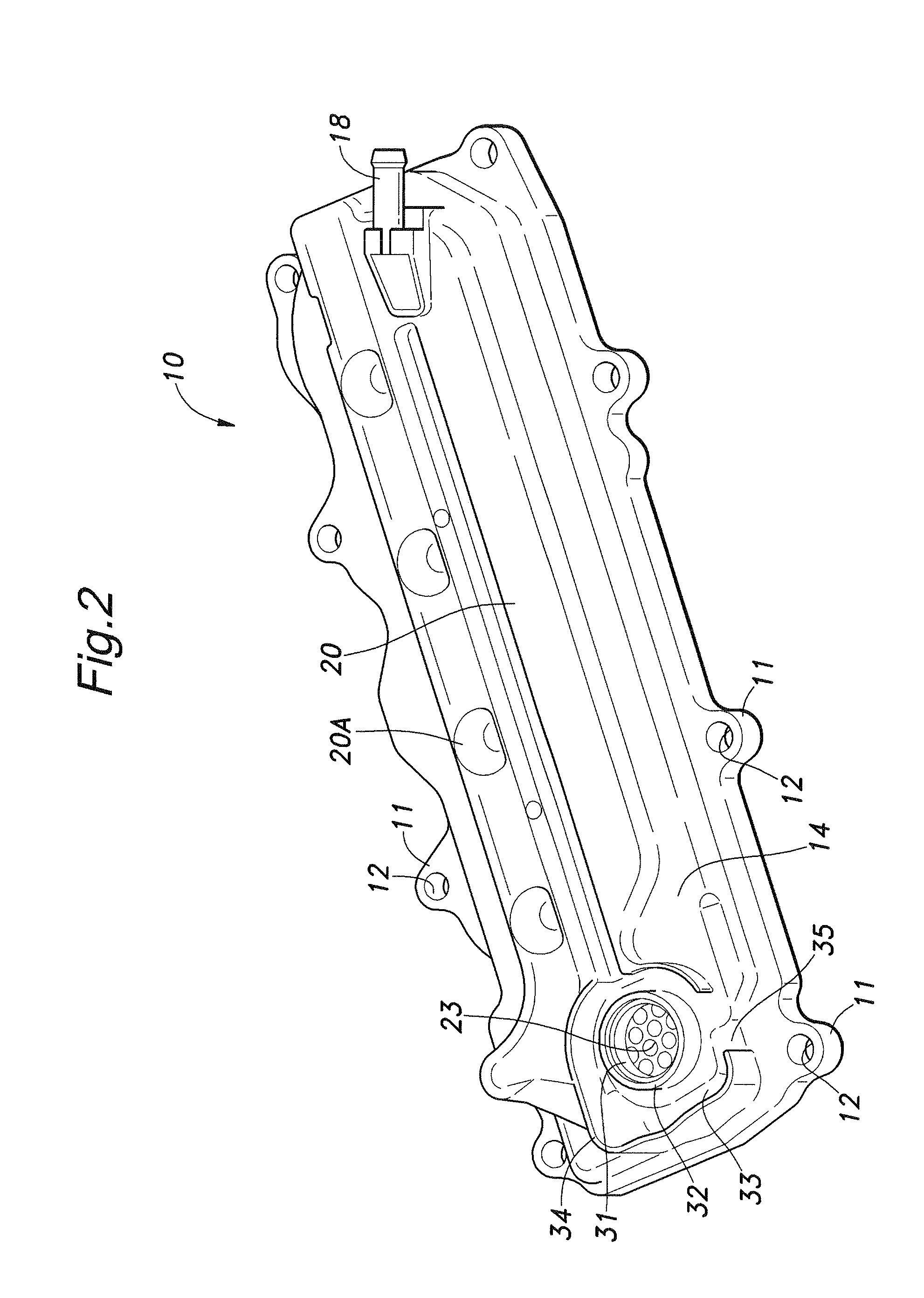
[0021]A head cover 10 according to this embodiment is used in a straight four-cylinder engine, and consists of a lid-like member extending in the direction of cylinder arrangement and made by molding a resin material such as glass-fiber reinforced polyamide resin. The head cover 10 is securely fastened to an upper surface of a cylinder head 50 by means of fastening bolts 13 passed through corresponding through holes 12 defined in bolt boss portions 11 which are formed at a plurality of locations along an outer periphery of the head cover 10.

[0022]An intake collection chamber (surge tank) 51 of an engine intake system is disposed close to an outer surface of a ceiling wall 14 of the head cover 10. The intake collection chamber 51 of the engine intake system herein includes an intake collection chamber of an intake manifold and a surge tank. In...


PUM


Abstract

A part of a ceiling wall (14) of a head cover (10) that opposes an intake collection chamber (51) is constituted by a concave ceiling wall (20) that defines a concave surface facing the intake collection chamber (51), and the concave ceiling wall (20) is formed with a recessed groove (21) that further recedes toward an inner side of the head cover.

Description

TECHNICAL FIELD[0001]The present invention relates to a head cover of an internal combustion engine, and particularly relates to a head cover in which a breather chamber of a blow-by gas is defined on an inner side of a ceiling wall of the head cover.BACKGROUND ART[0002]A head cover attached to a cylinder head of an internal combustion engine to cover a valve mechanism is sometimes formed with a breather chamber (breather passage) on an inner side thereof such that a blow-by gas flows through the breather chamber in order to have an oil mist contained in the blow-by gas be separated from the blow-by gas (gas-liquid separation) (see Japanese Patent Application Laid-Open Publication No. 2005-155475, for example).[0003]For the purpose of achieving a compact arrangement of an intake system of the internal combustion engine, an intake collection chamber of an intake manifold or a surge tank may be disposed close to an upper side of the head cover. In such a case, in order to cope with th...

Claims


Application Information

Patent Timeline
IPC IPC(8): F02B25/06F02B77/00
CPCF01M13/0416F02F7/006F02M35/10078F02M35/112F02M35/10222F02M35/10288F02M35/10111
Inventor AKIYAMA, YOSHIHIROYOSHIMURA, ATSUSHIEMI, ISAO
Owner HONDA MOTOR CO LTD
Why Eureka
Try Eureka