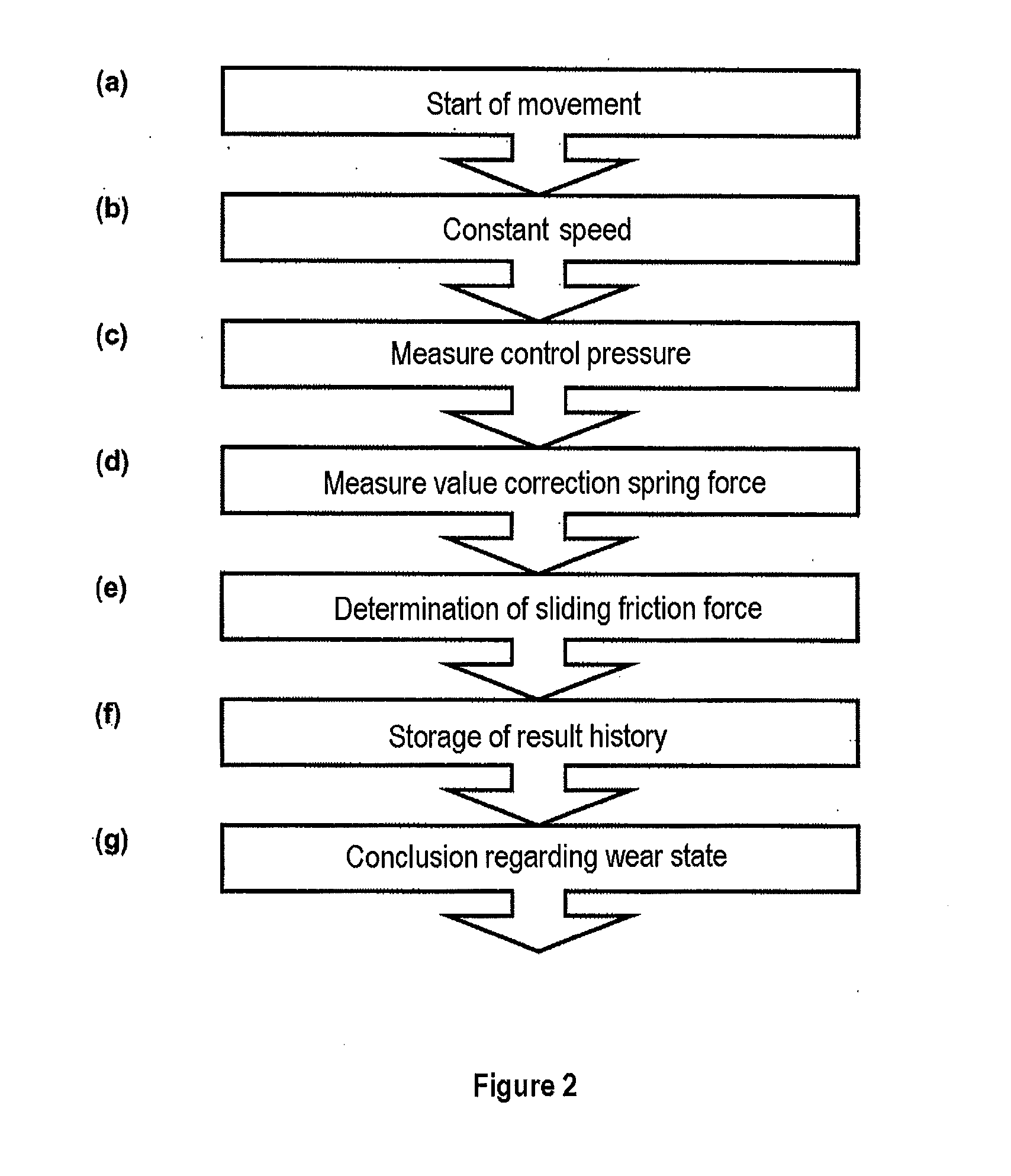
[0020]The disclosure includes an exemplary method whereby a valve element is moved at a
constant speed over at least a subarea of travel movement, the value of which speed can be measured via a
position sensor system for
signal processing. The currently applied control pressure can be measured at the same time (i.e., at approximately the same time within a specified tolerance such as within approximately 0.1 sec. or lesser, or greater) for
signal processing via a
pressure sensor system. The current sliding friction of the valve element can be determined as a measure of the wear state from both measured values, by means of an electronic evaluation unit, from a proportional drive force which is expressed by the control pressure which occurs when the valve element is traveling at a constant speed.
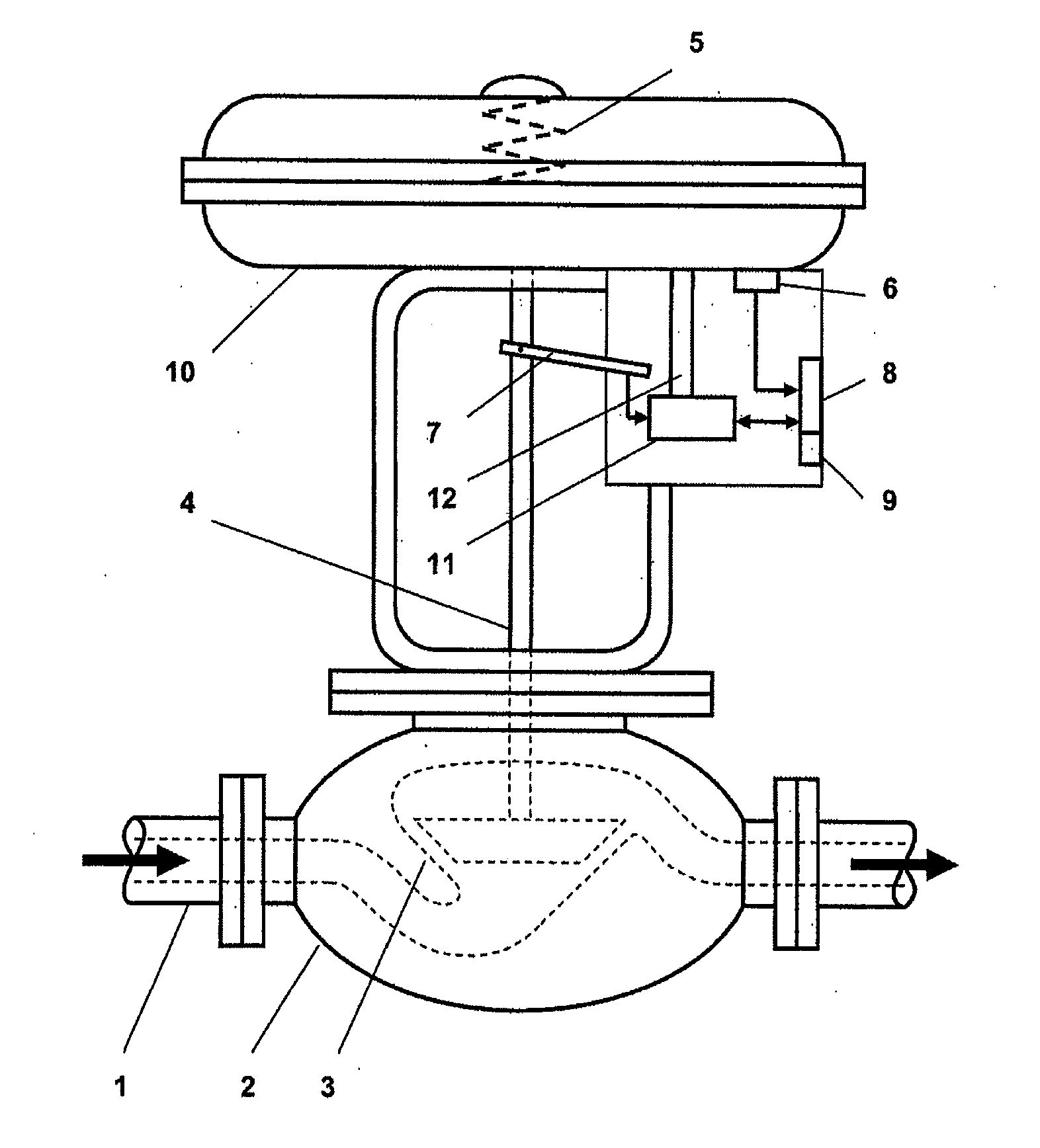
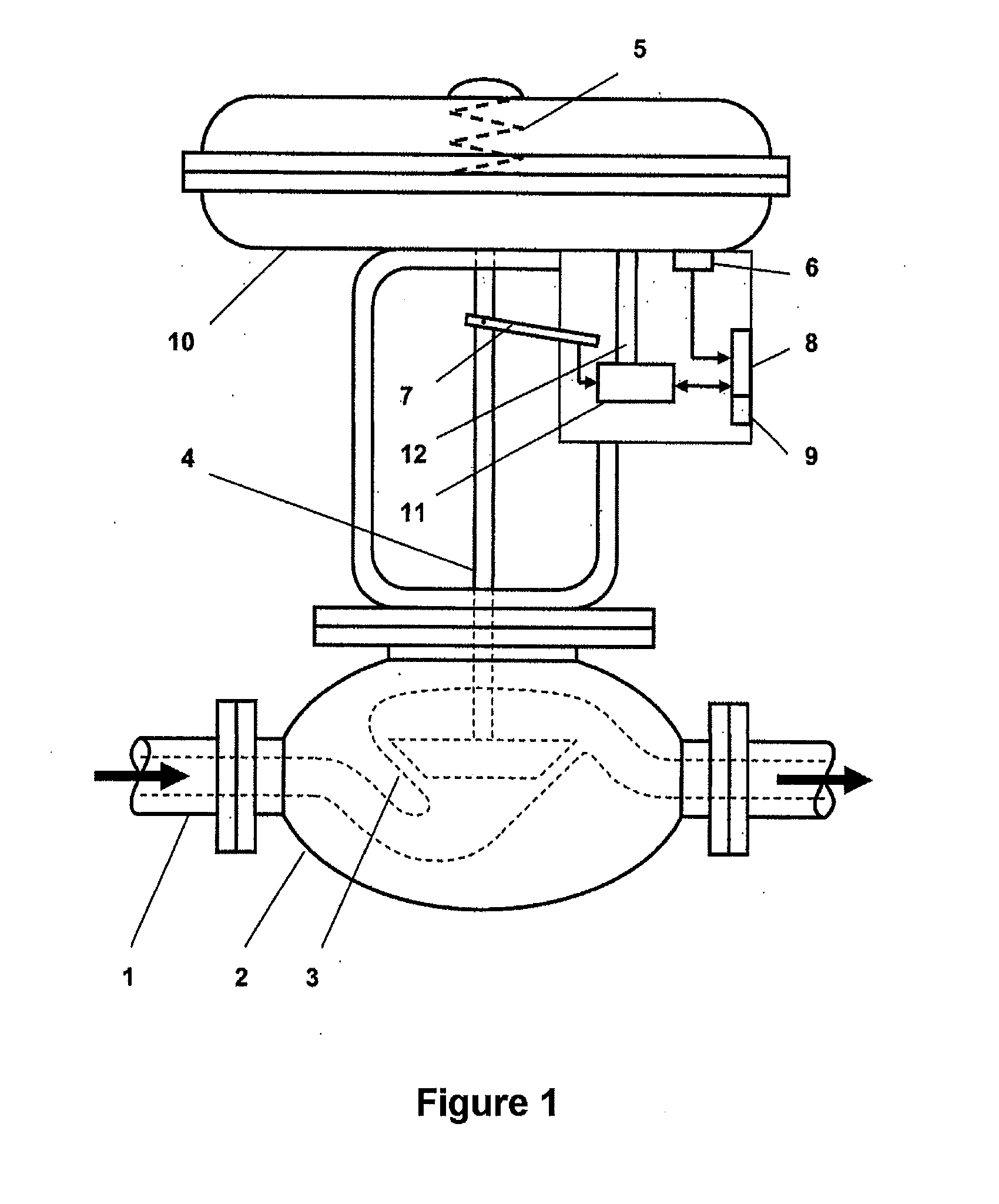
[0021]According to exemplary embodiments, a
position sensor system which measures the position of the valve element is combined in a specific manner with a
pressure sensor system which detects the control pressure to allow sliding friction values to be determined more accurately by making it possible to deduce progressive wear by comparison with historical sliding friction values. Since the position
sensor system provides an auxiliary way of determining the control pressure used for movement of the valve element when the valve element is moving at a constant speed, this makes it possible to very largely preclude disturbance influences that corrupt the measured value. This is because movement phases at a constant speed can eliminate disturbance influences which are caused by a pressure change in the
pneumatic valve or by
static friction.
[0022]The evaluation unit can compare the pressure measured value of at least two measurements, which are carried out with a time interval between them, for the same speed measured value in order to determine the wear state. The friction parameters can be calculated from the respective pressure measured values and the comparison process can be carried out to determine whether they have deteriorated, thus indicating progressive wear. In this case, the time interval should be chosen such that significant changes can be perceived by the measurement. Depending on the
switching frequency, this can invariably be done at an interval of, for example, several days. However, as an alternative to this, it is possible to detect the pressure measured values that are associated here for different speed measured values, in which case the friction parameters can be calculated from the respectively obtained value pairs, taking account of the speed difference.
[0023]As start conditions for an exemplary method, the two measured values can be detected when the valve element is moving in a stable manner at a constant speed, starting from one of the rest positions, and with the corresponding
static friction having been overcome. As referenced herein, a “constant” speed is a speed which is sufficiently stable (i.e., substantially stable relative to the operating range of the valve element) as to make it possible to reliably detect sliding friction in the manner disclosed herein. This makes it possible to reliably preclude initial
static friction influences on the speed profile of the valve element.
[0028]As an exemplary alternative to this, in order to achieve a constant speed of the valve element, the
pilot valve which is used for application of the control pressure may also be in the form of an I / P converter with a constant nominal value preset. The
constant pressure which can be achieved by an I / P converter makes it possible to produce a constant drive force which results in the actuating element moving at a constant speed, at least over a portion of its travel distance. The I / P converter can then be controlled such that it produces a constant
mass flow or a
constant pressure difference, which results in the desired constant speed of the valve element.
[0025]An exemplary evaluation unit can determine the value of the current sliding friction by means (e.g., a
software module) which establishes a simplified proportional
mathematical relationship to the drive force calculated for the pressure measured value. This simple measure can be used because of the direct relationship between current sliding friction and the drive force to be applied to move the valve element during a phase-constant speed.
[0029]However, it is also possible to completely dispense with
active components for producing a constant speed, as a result of which a measurement of the control pressure which is applied can be carried out by the pressure
sensor system in the event of a randomly occurring constant speed of the valve element, which can be detected via the position
sensor system. However, this exemplary approach recognizes that it may not be possible to move the valve element at a desired speed.

