Card holding apparatus

a technology for holding apparatuses and cards, applied in the field of cards holding apparatuses, can solve the problems of cumbersome process for loading or removing smart cards, inability to secure waterproof properties, and difficulty in adopting waterproof structures, and achieve the effect of easy loading and removal

Active Publication Date: 2010-06-17
PANASONIC CORP
View PDF6 Cites 3 Cited by
  • Summary
  • Abstract
  • Description
  • Claims
  • Application Information

AI Technical Summary

Benefits of technology

[0010]It is an object of the present invention to provide a card holding apparatus that facilitates loading and removal of a smart card and yet can be waterproofed.
[0012]According to the present invention, since the seal member is disposed only around the terminal, and a structure in which the contact terminals can be hermetically sealed by rotating the lid to the position opposite and in close proximity to the principal face of the housing is employed, the smart card can be loaded and removed easily and the contact terminals also can be protected from water.

Problems solved by technology

Since the card holding apparatus has the directly exposed terminal electrode disposed in the opening into or from which the smart card is inserted or removed, it is difficult to adopt a waterproof structure.
In other words, since water can enter the card holding apparatus through the opening for insertion of the smart card, waterproof properties cannot be secured.
Accordingly, the processes for loading or removing the smart card are cumbersome.

Method used


Image

  • Card holding apparatus
  • Card holding apparatus
  • Card holding apparatus

Examples


embodiment

1. Configuration of Card Holding Apparatus

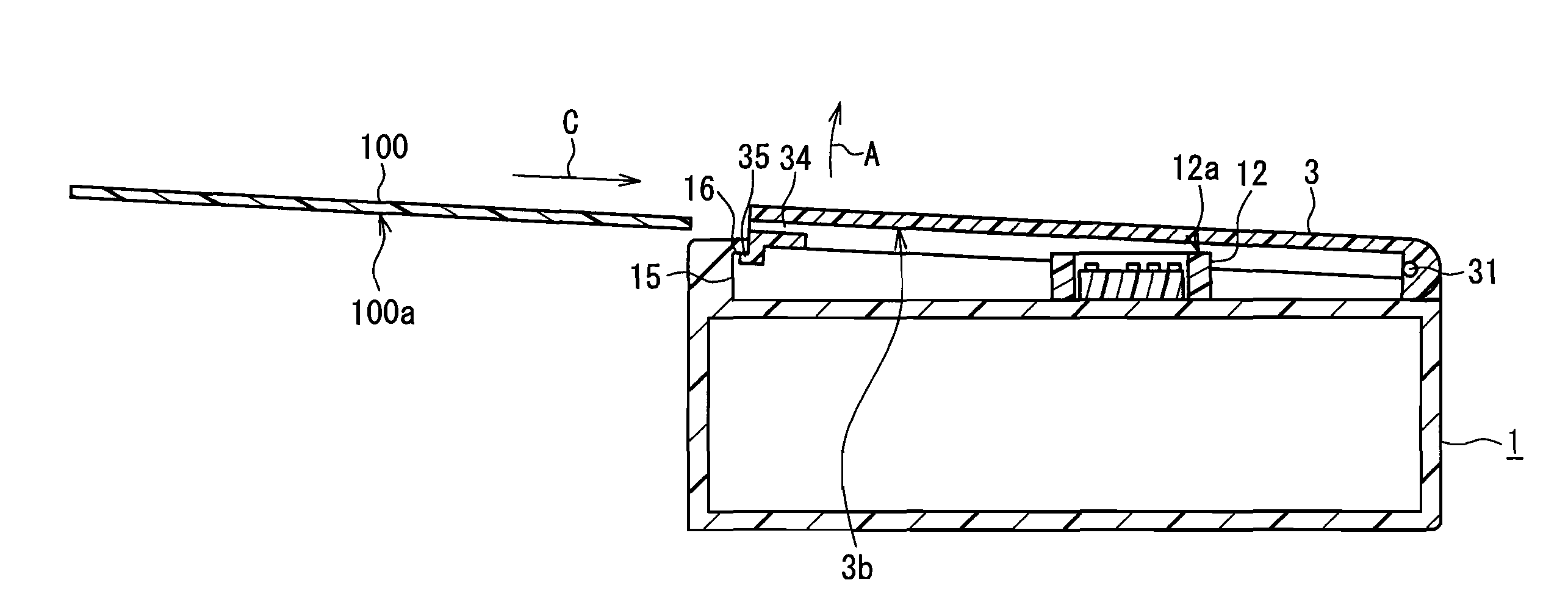
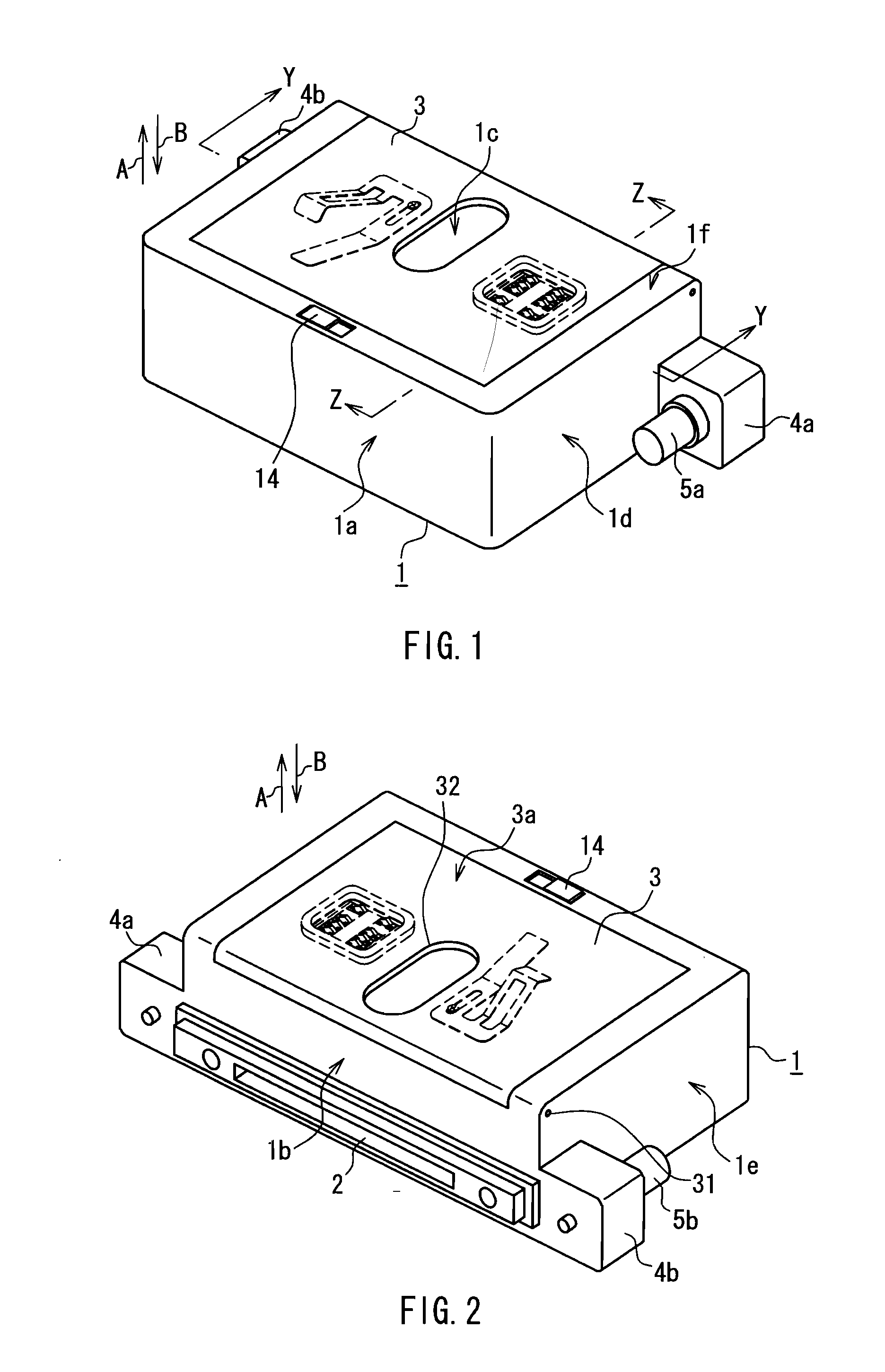
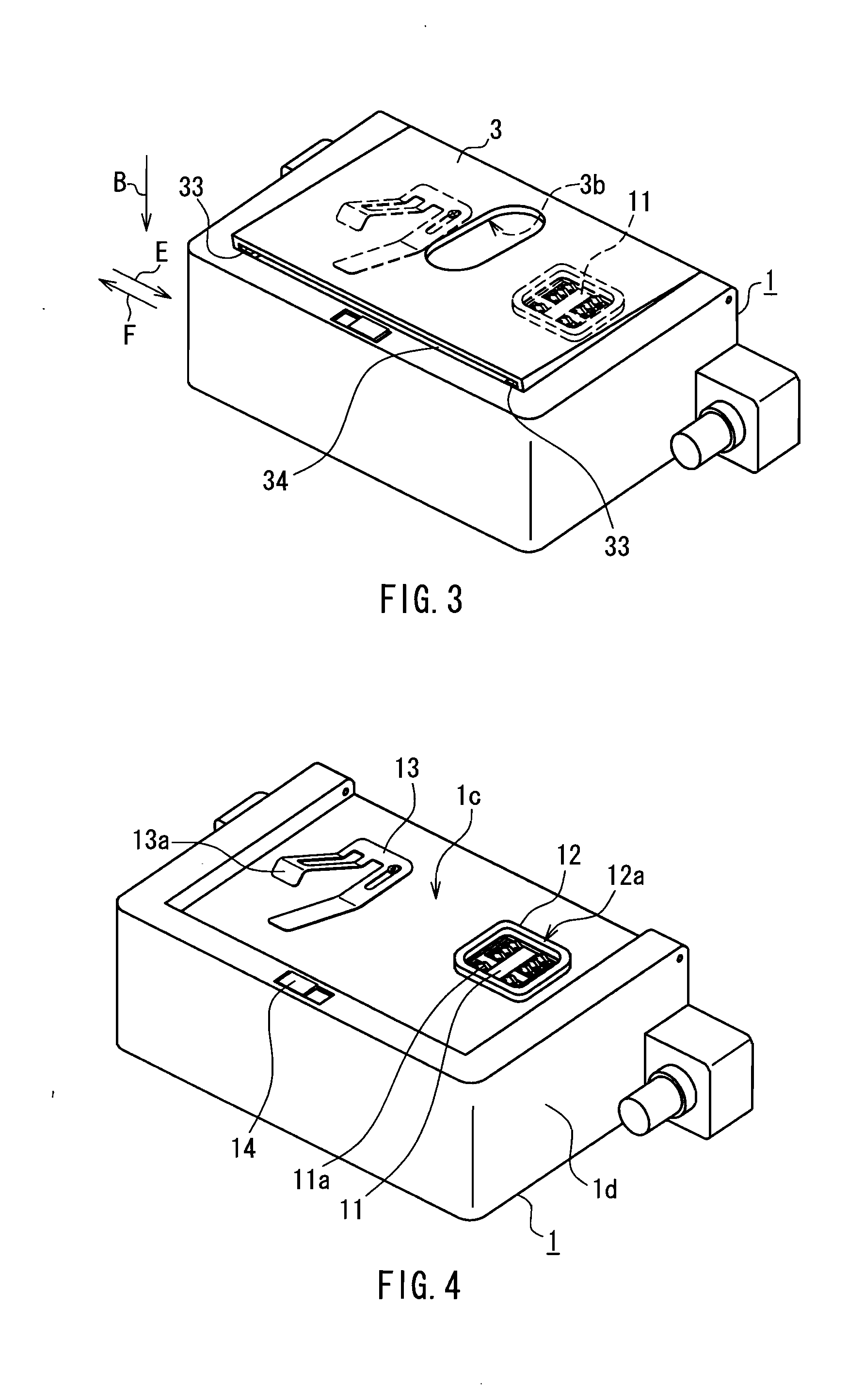
[0035]FIG. 1 is a perspective view showing an appearance (on the front face side) of a card holding apparatus according to an embodiment. FIG. 2 is a perspective view showing an appearance (on the rear face side) of the card holding apparatus according to the present embodiment. FIG. 3 is a perspective view showing the card holding apparatus in a state in which a lid is open.

[0036]As illustrated in FIGS. 1 and 2, the card holding apparatus includes a housing 1 that forms an approximately rectangular parallelepiped. The housing 1 has a built-in electrical circuit component. As illustrated in FIG. 2, a connector 2 is disposed in a rear face 1b of the housing 1. The connector 2 can be connected to various types of information processing apparatuses such as a personal computer 50, which will be described later with reference to FIG. 6. A rib 4a is formed on a right side face 1d of the housing 1 so as to protrude from said side face, which is a ...


PUM


Abstract

A card holding apparatus of the present invention includes a seal member 12 that is provided so as to surround the periphery of a contact terminal portion 11. When a lid 3 is positioned in a closed position with a smart card 100 retained by the lid 3, the seal member 12 comes into close contact with the periphery of a terminal 101. Thus, even when foreign matter such as water or dust intrudes into a space between the lid 3 and a housing 1, adhesion of such foreign matter to contact terminals 11a or the terminal 101 can be prevented.

Description

BACKGROUND OF THE INVENTION[0001]1. Field of the Invention[0002]The present invention relates to a card holding apparatus into which a card-type memory medium having a terminal on a principal face thereof can be loaded.[0003]2. Description of Related Art[0004]Recently, some information devices such as notebook computers are provided with a slot into which a card-type memory medium called “a smart card” can be loaded removably in order to improve security. Physical characteristics and electrical characteristics of smart cards are standardized based on the international standard ISO 7816. Moreover, in the Japanese Industrial Standard, the physical characteristics, the locations and the dimensions of external terminals, and the like of smart cards are defined in “JIS X 6303”. A smart card has a main body in the form of a card having dimensions of, for example, about 95 mm in width, about 54 mm in depth, and about 0.5 to 1.0 mm in thickness and an IC chip (an integrated circuit) built i...

Claims


Application Information

Patent Timeline
Patent Type & Authority Applications(United States)
IPC IPC(8): G06K7/06G06K7/00
CPCG06K13/0893G06K13/08
Inventor FUJITA, SHINJIYASUOKA, SYUJISHIMADA, ISAO
Owner PANASONIC CORP
Why Eureka
Try Eureka