Coupling device fitted with instantaneous or quasi-instantaneous anchor means

a technology of instantaneous or quasi-instantaneous anchor means and coupling devices, which is applied in the direction of couplings, hose connections, pipe elements, etc., can solve the problem of impracticality of using such coupling devices

Active Publication Date: 2010-06-17
LEGRIS
View PDF11 Cites 17 Cited by
  • Summary
  • Abstract
  • Description
  • Claims
  • Application Information

AI Technical Summary

Benefits of technology

[0006]Thus, since the anchor member is held in the inactivation position, the anchor section may be engaged in the well without any particular manipulation of the cover, until the cover comes into abutment against the circuit element and is pushed back into its declutching position. The pressure in the circuit also tends to force the cover into the activation position and to press the cover against the circuit element so that a sealing element disposed between the circuit element and the cover presents increased effectiveness.
[0010]The structure of the first embodiment is thus particularly simple.
[0012]This arrangement provides instant coupling of the anchor section in the well without requiring the cover to be manipulated by the user.
[0014]This structure is particularly simple and is found to be easy to make.
[0016]The anchor member then provides reliable anchoring and is more particularly adapted to anchoring in a tapped well when the anchor ends are themselves threaded.

Problems solved by technology

That combination of movements makes using such coupling devices rather impractical.

Method used


Image

  • Coupling device fitted with instantaneous or quasi-instantaneous anchor means
  • Coupling device fitted with instantaneous or quasi-instantaneous anchor means
  • Coupling device fitted with instantaneous or quasi-instantaneous anchor means

Examples


first embodiment

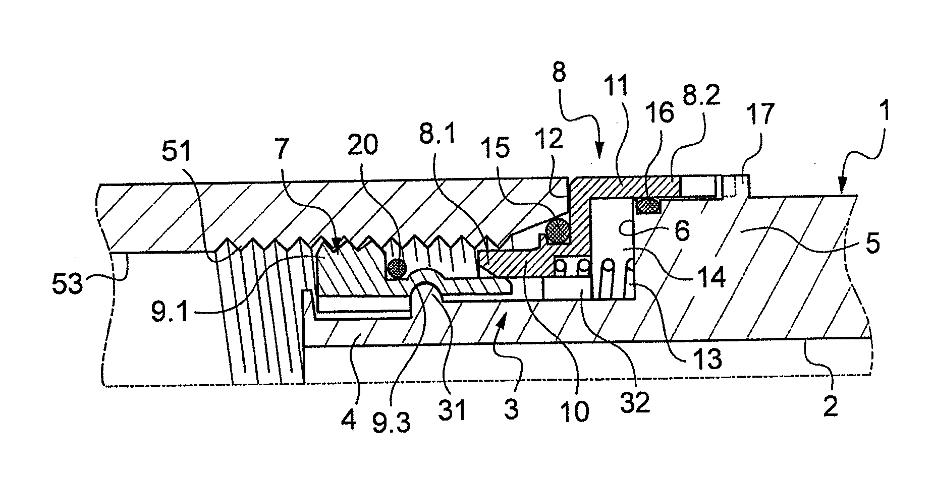
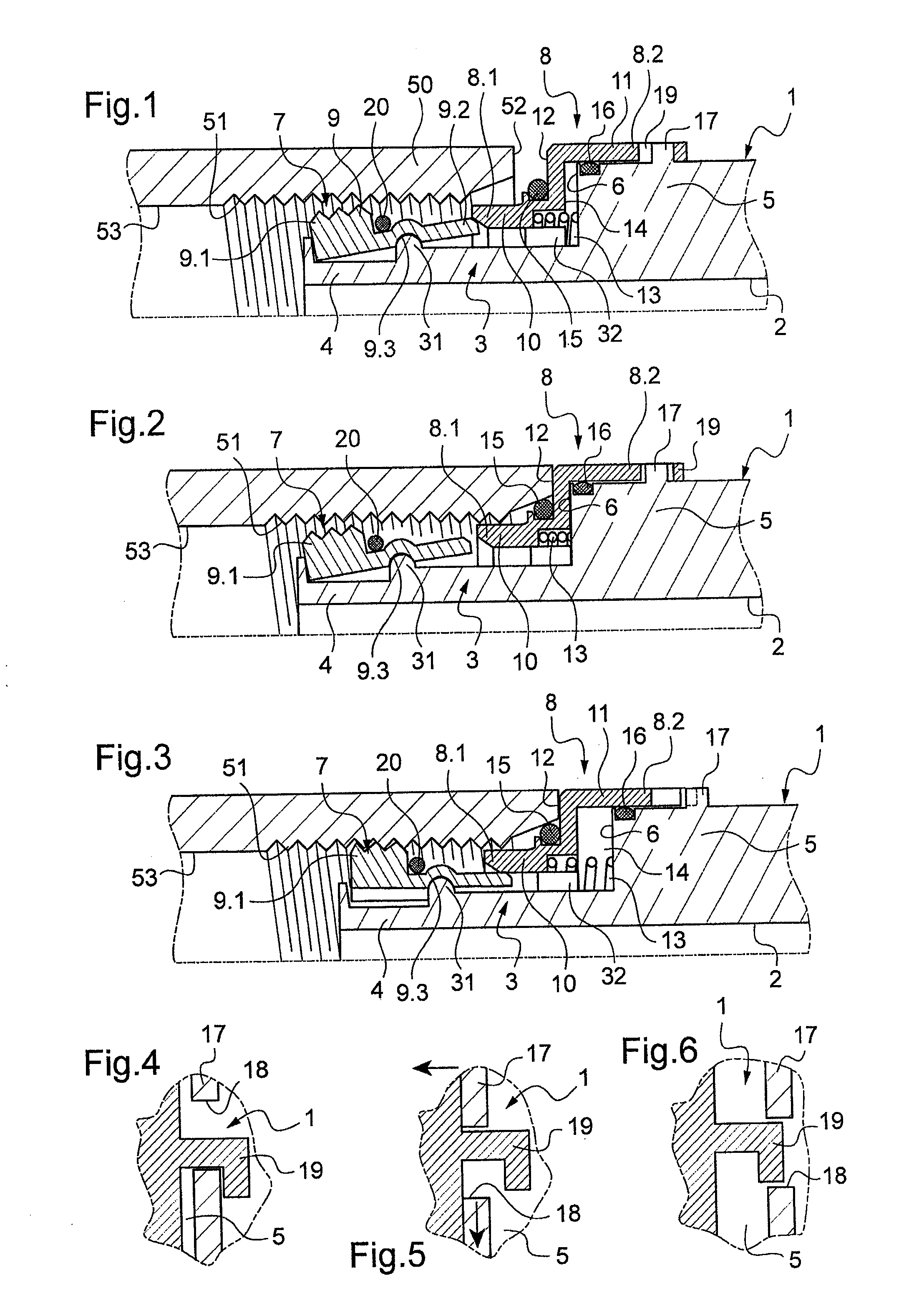
[0038]In the first embodiment, the holder means, the cover 8, and the body 1 are arranged in such a manner that the cover 8 in the declutching position is capable of pivoting so as to leave it free to slide towards the activation position. In this example the holder means comprise at least one portion in relief secured to the body, and the drive end 8.2 of the cover 8 has a gripper member for gripping the portion in relief when the cover 8 is in the inactivation position, it being possible for the cover 8 to be pivoted when it is in the declutching position so as to disengage the portion in relief from the gripper member. The portion in relief is a collar 17 that extends around the link portion 5, the collar 17 being interrupted by an opening 18. The gripper member comprises a hook 19 extending axially from the drive end 8.2.

[0039]When the cover 8 is in the inactivation position (FIGS. 1 and 4), the hook 19 extends in the opening 18 and is engaged on one end of the collar 17 at the ...

second embodiment

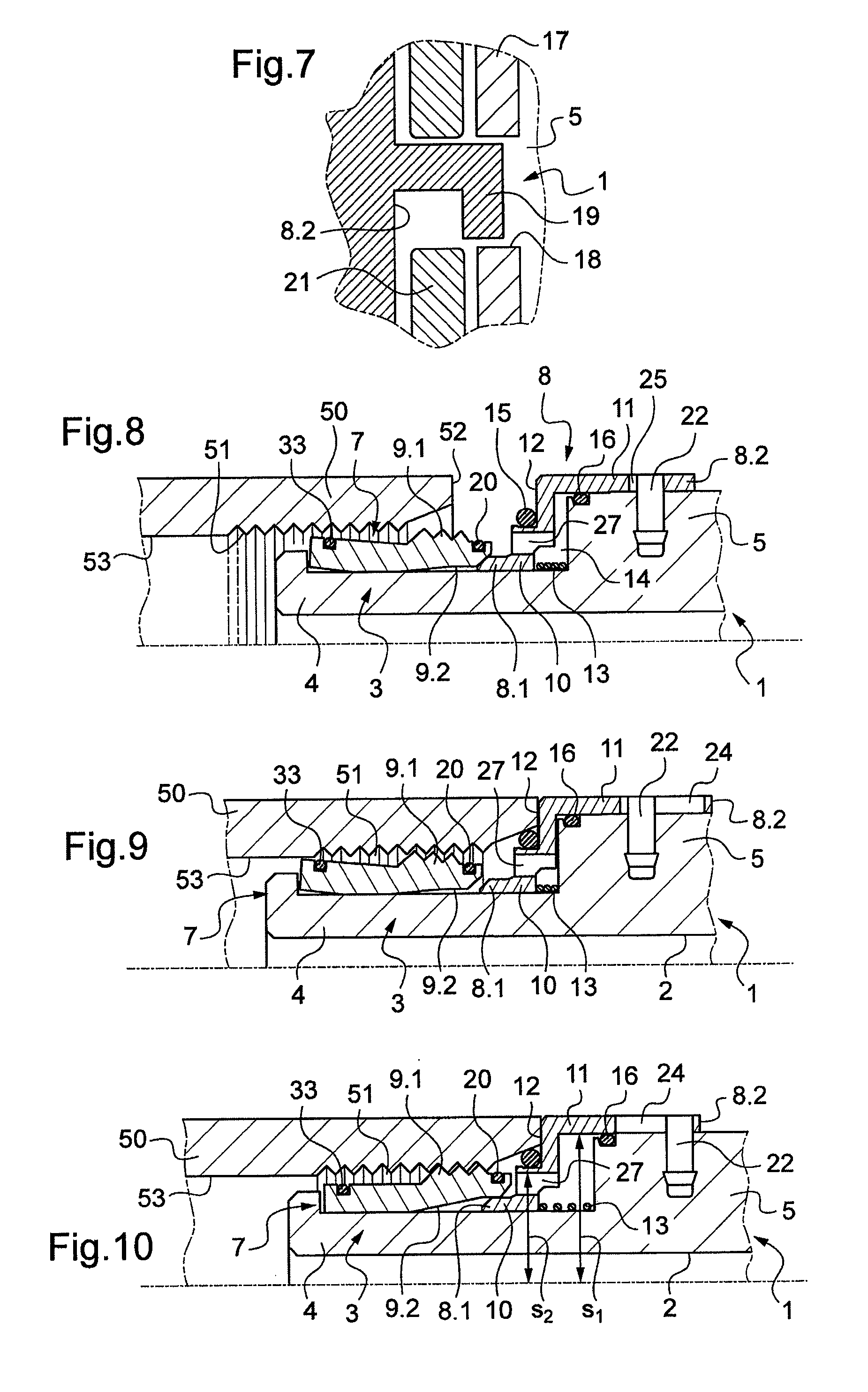
[0044]In the second embodiment, shown in FIGS. 8 to 14, the drive portions 9.2 of the sectors 9 are arranged on the anchor ends 9.1 that extend, in this example, beside the cover 8 and the drive end 8.2 of the cover 8, is arranged to engage under said drive portions so as to move them apart from one another when the cover 8 is in the activation position. The sectors 9 bear against the end portion 4 via curved portions. In FIG. 10, the section of the cover 8 beside the chamber 14 is referenced s1 and the section of the cover 8 beside the well 51 is referenced s2, and in accordance with the invention, the chamber side section s1 of the cover is greater than the well side section s2 of the cover.

[0045]A resilient metal ring 33 surrounds the ends of the sectors 9 remote from their anchor ends 9.1 so as to hold them together. The cover 8 includes at least one opening 27 arranged in the front wall of the cover.

[0046]The holder means for holding the cover 8 in the inactivation position com...


PUM


Abstract

A coupling device comprising a tubular body defining a channel and axially subdivided into an anchor section provided on the outside with an anchor member associated with a cover mounted on the body to have both an actuator end for actuating the anchor member and a drive end, and so as to be movable between an inactivation position and an activation position, a resilient return member urging the cover towards the activation position being mounted in a chamber defined by the cover and the body, the cover having holder means for holding it in the inactivation position, which holder means are arranged to be declutchable when the cover is moved into a declutching position beyond its inactivation position in a direction away from the activation position, and the device including communication means for putting the chamber into communication with the well, the cover presenting a section beside the chamber that is greater than its section beside the well.

Description

CROSS-REFERENCE TO RELATED CASES[0001]The present application claims the benefit of the filing date of French Patent Application Serial No. 08 06982, filed Dec. 12, 2008, the disclosure of which is expressly incorporated herein by reference.BACKGROUND OF THE INVENTION[0002]The present invention relates to a coupling device for coupling a duct end to a fluid-transport circuit element. The device is suitable for use in particular for coupling a pipe to a fluid-emitting or receiving element, such as another pipe, a manifold, an actuator, a tank, a pressure or flow rate sensor, etc.[0003]The coupling device generally comprises a tubular body defining a channel that is axially subdivided into an anchor section for anchoring the body in a well of the circuit element and a connection section for connection to the duct end. The anchor section is provided on the outside with an anchor member that has an anchoring state and a releasing state. The anchor member is associated with a cover mount...

Claims


Application Information

Patent Timeline
Patent Type & Authority Applications(United States)
IPC IPC(8): F16L37/08
CPCF16L37/1215F16L37/107
Inventor LE QUERE, PHILIPPE
Owner LEGRIS
Why Eureka
Try Eureka