Gripper device and module for its construction

Inactive Publication Date: 2010-06-17
GIMATIC SRL
View PDF7 Cites 10 Cited by
  • Summary
  • Abstract
  • Description
  • Claims
  • Application Information

AI Technical Summary

Benefits of technology

[0007]Therefore, the gripper device of the invention becomes simpler and lighter and incorporates a plurality of prehensile flexible elements with a respective control module in order to form together a contractible / expandable system. By an appropriate choice of the number of gripper modules it is possible construct devices of various dimensions in relation to the dimensions of the articles to be gripped. Furthermore, by orienting differently the prehensile elements towards the inside or outside of the supporting body, it is also possible to prepare from time to time gripper devices suitable for gripping articles on the outside or, if hollow, on the inside.
[0008]The prehensile elements can have a considerable width, and therefore be more robust, wear resistant and long lasting and efficient in time. Besides, each prehensile element can act alone or with the help of at least a spring, as an elastic means to return the device to the idle position following each activation in the presence of a single effect pneumatic actuator piston. Furthermore, every prehensile element or also the respective control module can be easily replaced without having to substitute or eliminate any other component of the device.
[0009]Also, the gripper device can operate under very high pressure, however not limited, to be able to develop higher gripper forces, in that the prehensile elements, by not having to be inflated no risk of explosion is run. This also enables the need for a pressure regulator to be avoided, besides which is expensive, as is required for the above mentioned gripper device belonging to the known technique.

Problems solved by technology

Such a device however has drawbacks at least regarding the fact that the prehensile element must have walls which are relatively thin and the working pressure must be in relation to the thickness of the walls in that if its maximum level is not limited it could break it, making the device inserviceable.
So, to avoid this possibility the inflatable air chamber must also be connected to a pressure regulator, which contributes to further increasing the weight of the device.

Method used


Image

  • Gripper device and module for its construction
  • Gripper device and module for its construction
  • Gripper device and module for its construction

Examples


Embodiment Construction

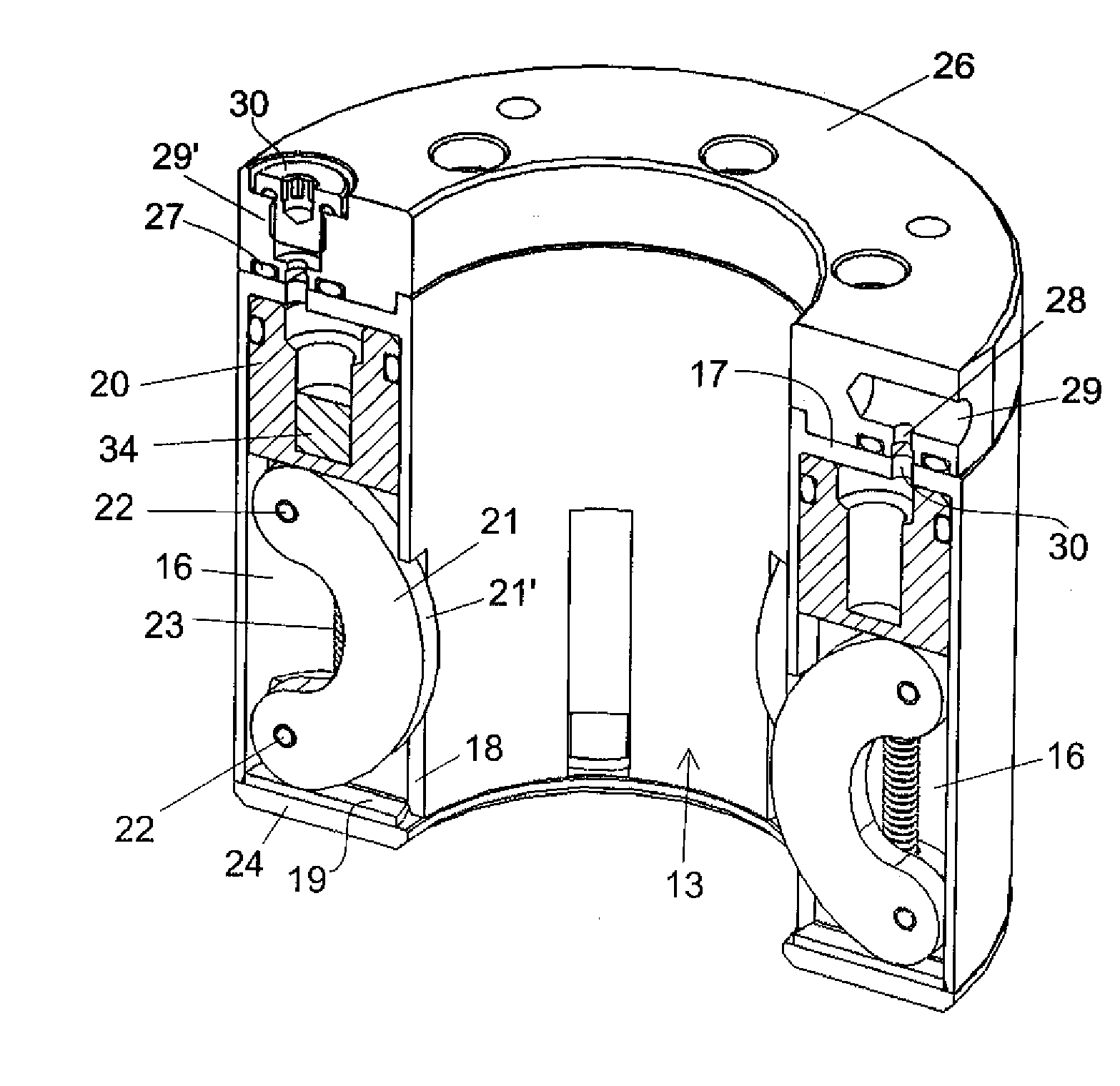
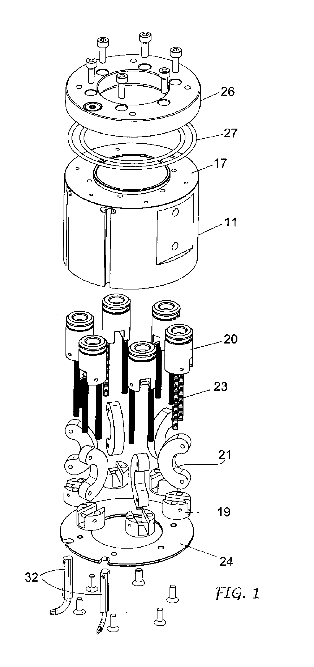
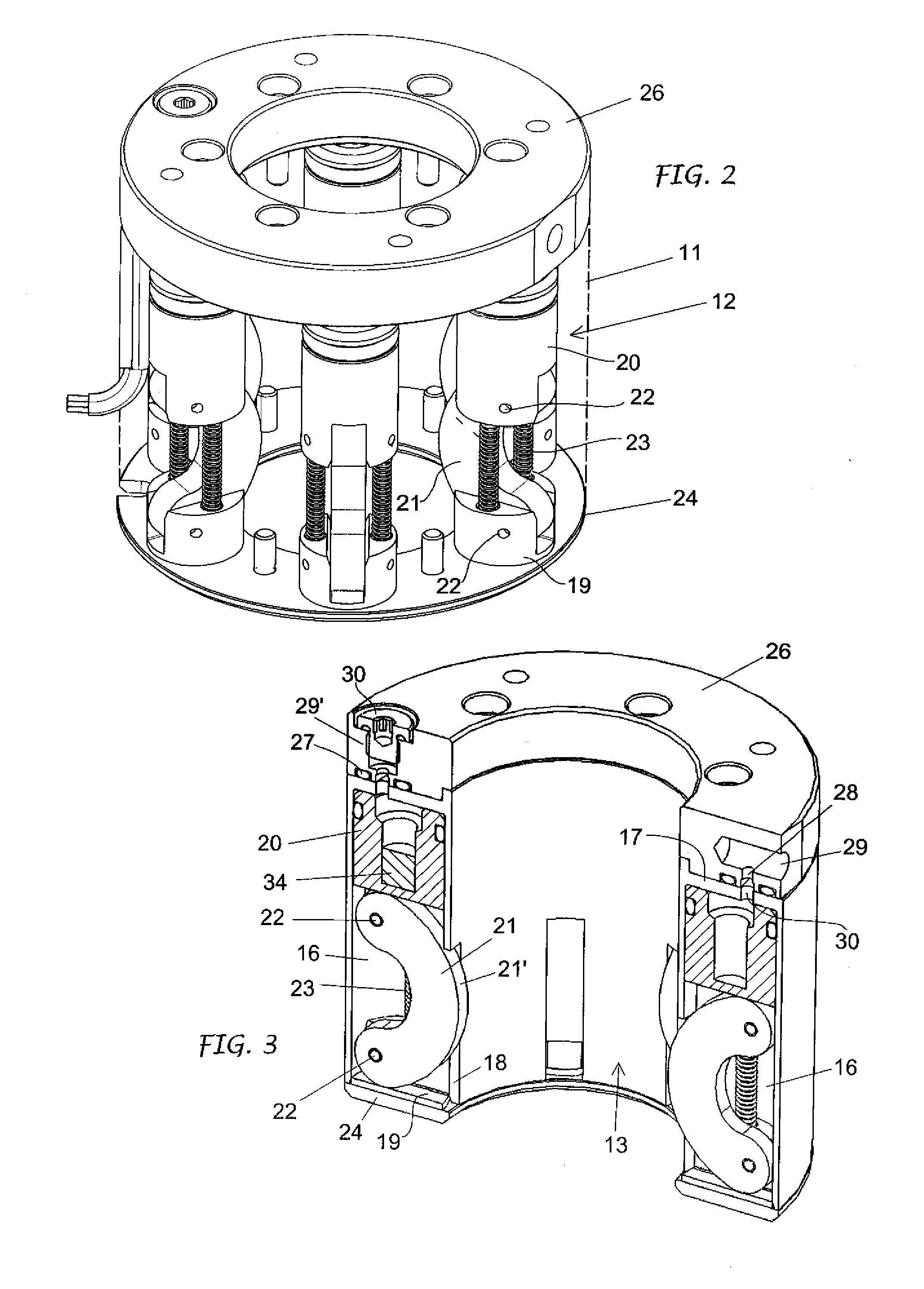
[0023]FIGS. 1-11 show gripper device 10 in a version to grip items, objects or bodies 100 on the outside. It is basically made up of a supporting body 11 and a plurality of identical gripper modules 12.

[0024]The supporting body 11 has its own geometric X axis and has an axial bore 13, a proximal part 14, a distal part 15; externally, it can be of any shape, but preferably cylindrical. In the supporting body 11, around the axial bore 13, several housings 16 are provided, the number depending on requirements and the dimensions of the device, which will be in relation to the dimensions of the items, objects or bodies to be gripped. In the example illustrated there are six housings 16, parallel to the X axis and distanced at an angle. Every housing 16 is closed at the supporting body proximal end by bottom wall 17, whereas it is open both at its distal end 15 of said body 11 and towards the axial bore 13 through a radial cleft or slot 18. The latter extends longitudinally for a length o...


PUM


Abstract

The invention concerns a gripper device for gripping solid or hollow items, objects or bodies, which comprises a supporting body (11, 11a) holding a plurality of gripper modules (12, 12a) positioned around the geometric axis of the body, parallel and spaced at an angle. Each module comprises a flexible prehensile arch-shaped element (21, 21a) having an extrados in line with a radial slot (18, 18a) along one side of said housing and engaged by an actuator piston. All the prehensile elements are movable between a decontracted rest condition, in which their extradossis are retracted in the respective slots (18, 18a), and a compressed / contracted work condition, in which their extradossis protrude from said radial slots (18, 18a) to engage from time to time the item, object or casing to be gripped.

Description

FIELD OF THE INVENTION CONSTRUCTION[0001]This invention concerns in general the grippers for manipulator devices, and in particular refers to a pneumatic control gripper device able to grip items, objects and bodies on the outside or inside for displacing or handling them.STATE OF THE TECHNIQUE[0002]Among the means for gripping and handling items, objects and various types of bodies during their manufacturing and / or handling and assembly processes, already well known are pneumatically controlled devices that comprise a gripper element, that is prehensile, basically tubular, made of an elastomeric material, such as rubber or the like, associated with a supporting body and having a double wall so as to define an annular air chamber. When it is idle, the gripper device is deflated and remains in a contracted position; to activate it, it is inflated by blowing in a fluid under pressure, usually air, into its annular chamber through a conduct provided in the supporting body in order to e...

Claims


Application Information

Patent Timeline
IPC IPC(8): B25J15/02B66C1/42B66C1/54B66C1/44B25J15/00
CPCB25J15/12B65G47/908B65G47/90
Inventor MAFFEIS, GIUSEPPE
Owner GIMATIC SRL
Why Eureka
Try Eureka