Weaving machine, yarn feeder and method for inserting a weft yarn

a weft yarn and feeder technology, applied in the field of weaving machines, can solve the problems of insufficient work of the known yarn feeder, insufficient work of the passive balloon breaker, etc., and achieve the effects of low disturbance quota, high weaving speed, and considerable weaving width

Inactive Publication Date: 2009-04-23
IRO AB
View PDF23 Cites 3 Cited by
  • Summary
  • Abstract
  • Description
  • Claims
  • Application Information

AI Technical Summary

Benefits of technology

[0007]The weaving machine processes coarse yarn qualities with an extremely low quota of disturbances even in heavy duty applications when weaving fabric with considerable weaving width and extremely high weaving speed because the actively controlled yarn control elements, acting in addition to the passive balloon breaker on the region of the storage body between the yarn store and the withdrawal rim, assure that at the end of an insertion, and prior to the start of a subsequent insertion, the weft yarn is prevented from becoming entangled. The mechanical influence of the yarn control elements, i.e. of at least one of the yarn control elements, on the withdrawn weft yarn reliably suppresses a balloon formation in the region of the yarn control elements and assures that after the insertion the weft yarn does not get slacky and that the front most windings in the yarn store do not lose their correct order. The yarn control elements only impart the mechanical influence on the weft yarn beginning with the end phase of the insertion but are held in their rest position during the main part of the insertion. The balloon suppressing effect of the yarn control elements then also assists the balloon suppressing effect of the passive balloon breaker to assure that the weft yarn follows an orderly path inside the balloon breaker during the end phase of the insertion and after the insertion of the weft yarn has stopped. When a subsequent insertion is started, the yarn control elements are already brought into the rest positions such that the weft yarn takes an orderly, unobstructed course from the yarn store over the withdrawal rim into the balloon breaker. The high acceleration of the weft yarn in the start phase of the subsequent insertion is not at all negatively influenced by the yarn control elements. Controlling the weft yarn beginning with the end phase of the insertion by the yarn control elements reliably prevents the weft yarn from becoming entangled. This avoids operation disturbances and undesirable fabric faults even in the case of very coarse yarn qualities such as band-shaped yarns made from polypropylene.
[0008]In the yarn feeder, the temporary engagement of the actively controlled yarn control elements beginning with the end phase of insertion is of assistance for the balloon suppressing effect of the passive balloon breaker and assures that no critical entanglements occur neither when an insertion is terminated nor before the subsequent insertion is started.

Problems solved by technology

On such newly developed weaving machines, it has been found that a passive balloon breaker does not work satisfactorily enough because weft yarn very frequently becomes entangled in the region between the withdrawal rim of the storage body and the balloon breaker.
However, for heavy duty applications, the known yarn feeder does not work properly because the weft yarn may form entangled yarn loops between subsequent insertions in the region upstream from the entrance into the output brake.
In a heavy duty application, the weft yarn tends to get entangled around the front end of the storage body.

Method used


Image

  • Weaving machine, yarn feeder and method for inserting a weft yarn
  • Weaving machine, yarn feeder and method for inserting a weft yarn
  • Weaving machine, yarn feeder and method for inserting a weft yarn

Examples


Embodiment Construction

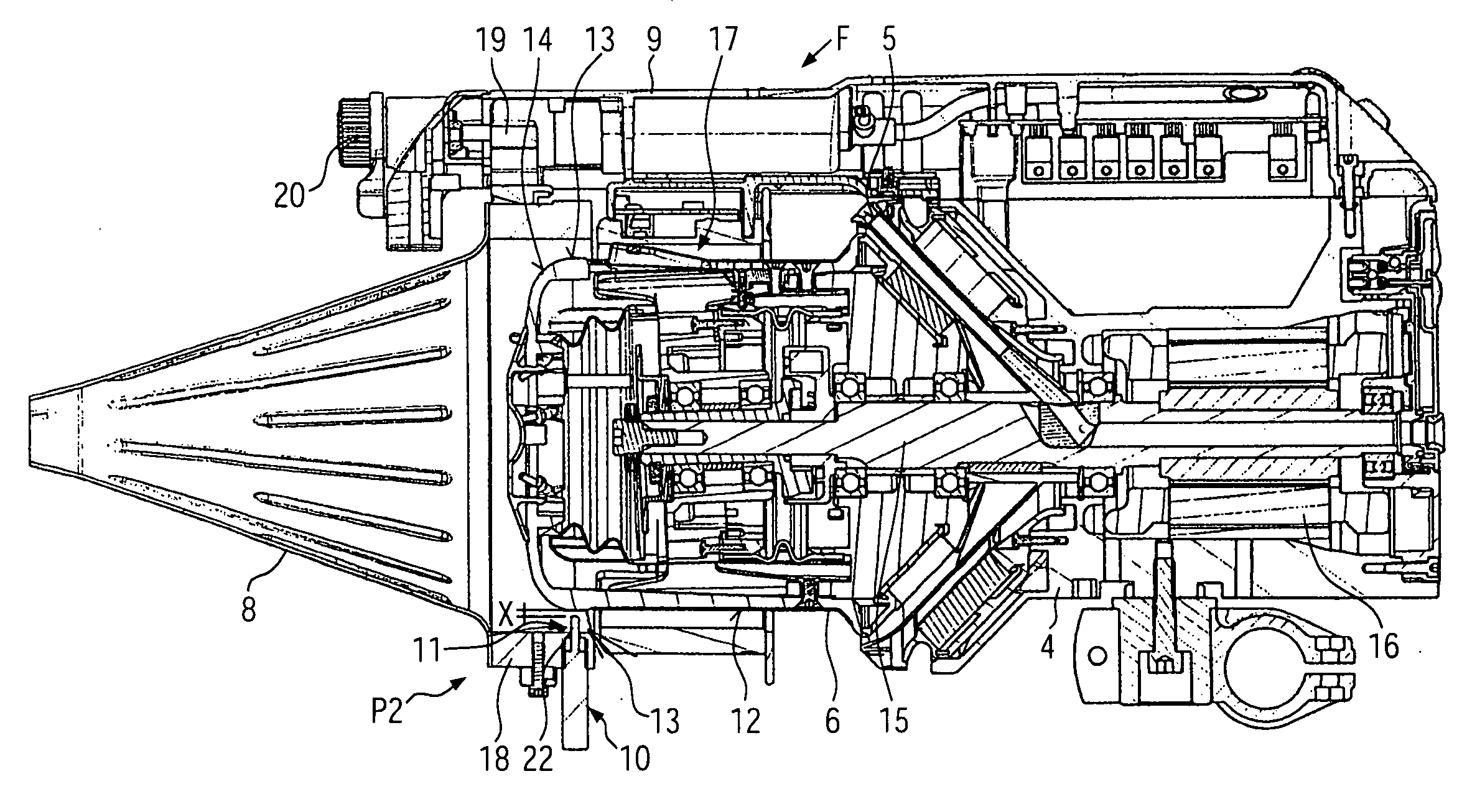
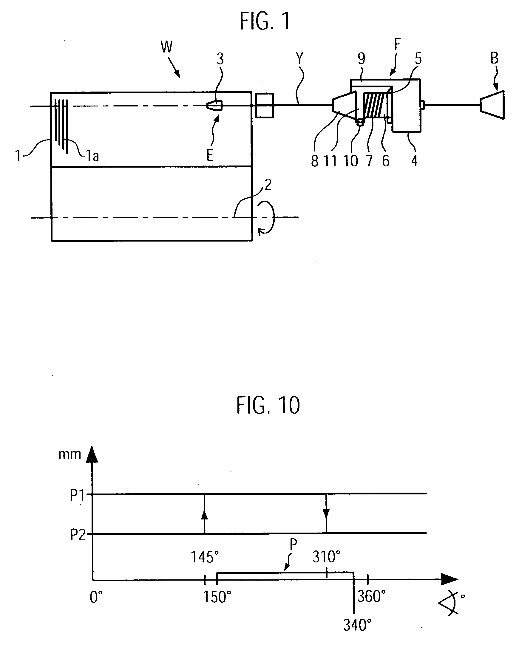
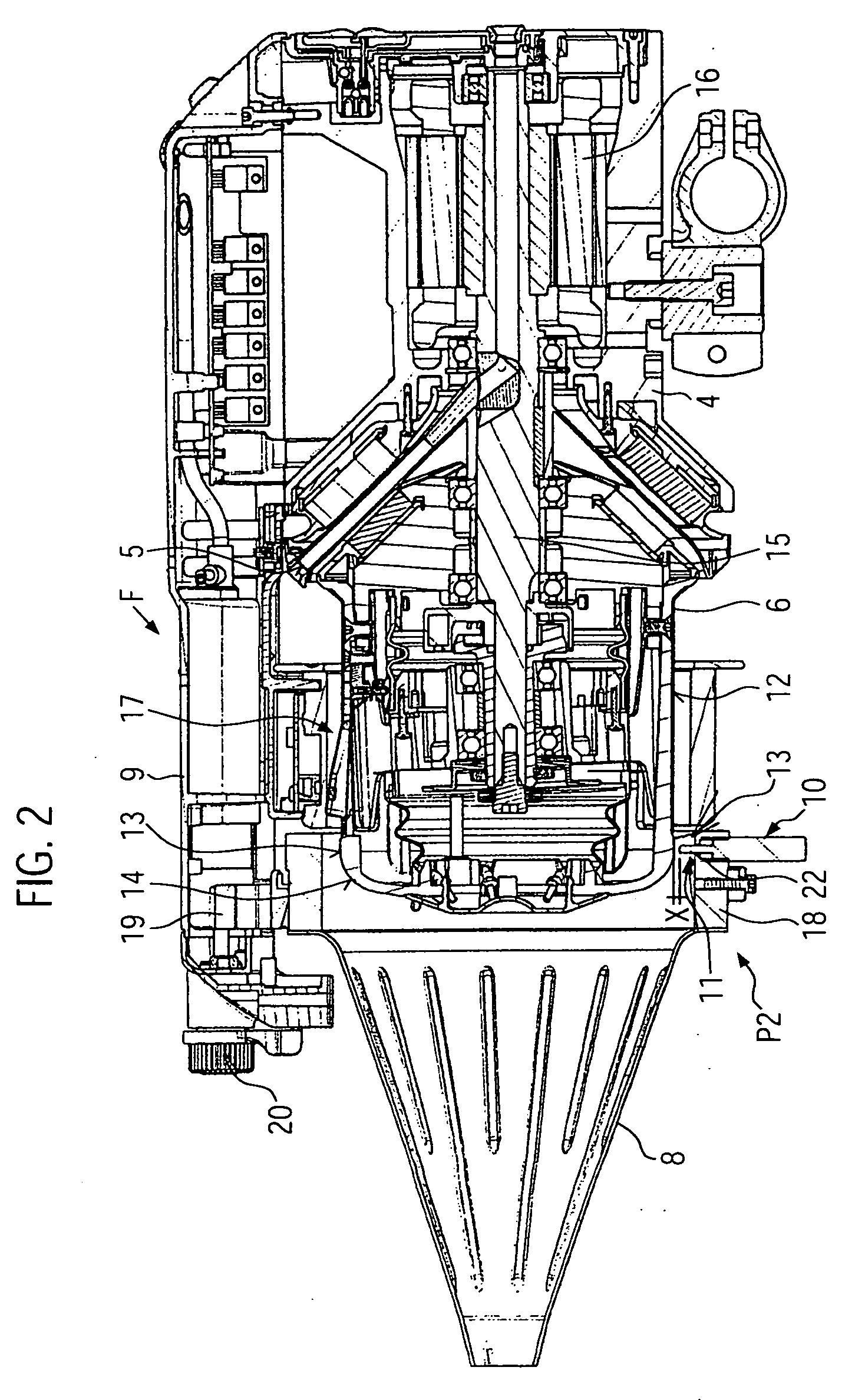
[0034]A weaving machine W, schematically shown in FIG. 1, comprises a weaving shed 1 having a reed la driven by a main shaft 2 of the weaving machine. One of a plurality of projectiles 3 serves as an insertion element E for inserting a weft yarn Y into the weaving shed 1. The weft yarn Y is intermediately stored in a yarn store 7 on a stationary storage body 6 of a weft yarn feeder F which takes off the weft yarn Y from a storage bobbin B. The weft yarn feeder F has a housing 4 and a winding-on-element 5 which can be driven for rotation by a motor 16 in relation to the stationary storage body 6 which might have substantially the form of a drum. A housing bracket 9 supports a hollow passive balloon breaker 8 (e.g. a balloon breaker cone) aligned with the storage body 6 such that the withdrawn weft yarn Y has to pass through the passive balloon breaker 8. Furthermore, several yarn control elements 11 are provided which can be actively driven by either a common or by separate drives 10...


PUM


Abstract

A projectile-weaving machine is equipped with a weft yarn feeder having a stationary storage body for intermediately storing a yarn store consisting of windings, the weft feeder comprising a passive hollow balloon breaker functionally associated to a withdrawal rim of the storage body. In addition to the passive balloon breaker, several yarn control elements are separated in circumferential direction for being actively moved by a drive from an outer rest position into an inner operative position which without totally stopping withdrawn weft yarn are brought into a mechanical engagement on the weft yarn upstream from the withdrawal rim and starting with an end phase of an insertion on the weft yarn while the weft yarn is taken off from the yarn store over the withdrawal rim.

Description

BACKGROUND OF THE INVENTION[0001]The present invention relates to a weaving machine having driven projectiles or rapiers, to a weft yarn feeder for a weaving machine, and to a method for inserting a weft yarn into a weaving machine.[0002]When weaving fabrics, there exist so called heavy duty applications meaning that coarse yarn qualities are woven such as heavy synthetic yarns or heavy synthetic bands, e.g. made from polypropylene. Special weaving machines are employed for heavy duty applications and also special weft yarn feeders designed to process such yarn qualities. Up to now it was considered to be sufficient to control the unavoidable yarn balloon occurring when withdrawing the weft yarn from the storage body of the yarn feeder with the insertion element of the weaving machine by a passive balloon breaker, e.g. a so-called balloon breaker cone as known from U.S. Pat. No. 5,769,132 A. However, newer and wider weaving machines for heavy duty applications have been developed wh...

Claims


Application Information

Patent Timeline
Patent Type & Authority Applications(United States)
IPC IPC(8): D03D47/36D03D47/48D03J5/00
CPCD03D47/364
Inventor GHIARDO, FIORENZO
Owner IRO AB
Why Eureka
Try Eureka