Device for controlling the transverse movement of the warp threads of a textile weaving machine

a technology of textile weaving machine and warp thread, which is applied in the direction of cam shedding mechanism, textiles and paper, dobbies, etc., can solve the problems of likewise taking up a relatively large amount of space, free oscillator, and type of shedding that has proved to be susceptible to faults, and achieves low space requirement, high weaving speed, and small electric drive motor

Inactive Publication Date: 2010-10-05
TEXTILMA AG
View PDF30 Cites 3 Cited by
  • Summary
  • Abstract
  • Description
  • Claims
  • Application Information

AI Technical Summary

Benefits of technology

[0011]In this case, the measures of the invention result, in the first place, in a very low space requirement, along with a high weaving speed. Due to the register-like fanning out of the heddle drives and to the spring assistance, it is possible to keep the electric drive motors small. Moreover, owing to the lever-like intensification, it becomes possible for the drive travel of these motors to be kept small.
[0012]It is advantageous if one at least double step-up is provided, that is to say a movement of the electric motors causes an at least twice as great a movement of the heddles.
[0013]A refinement with pull and push rods as force transmission elements for the drive of the driving elements, which may be generally conventional heddles, but, in a special case, also guide eyes, which are attached directly to the pull and push rods, affords, a simple embodiment of the invention.

Problems solved by technology

However, the version with the two springs in WO-A-98 / 24955 likewise takes up a relatively large amount of space, as may also be gathered from the drawings there.
Furthermore, it seems difficult, in the arrangement proposed in WO-A-98 / 24955, on the one hand, to keep the build of the electric motor small, but, on the other hand, to design it with such high power and high movement that it fulfills the requirements when a multiplicity of warp threads lying next to one another are to undergo shedding.
However, the principles of a free oscillator, which are already known from the document mentioned above, are not implemented by means of the device from EP 1 063 326 A1.
However, this type of shedding has proved to be susceptible to faults, since the retaining elements mentioned are basically temperamental.

Method used


Image

  • Device for controlling the transverse movement of the warp threads of a textile weaving machine
  • Device for controlling the transverse movement of the warp threads of a textile weaving machine
  • Device for controlling the transverse movement of the warp threads of a textile weaving machine

Examples


Embodiment Construction

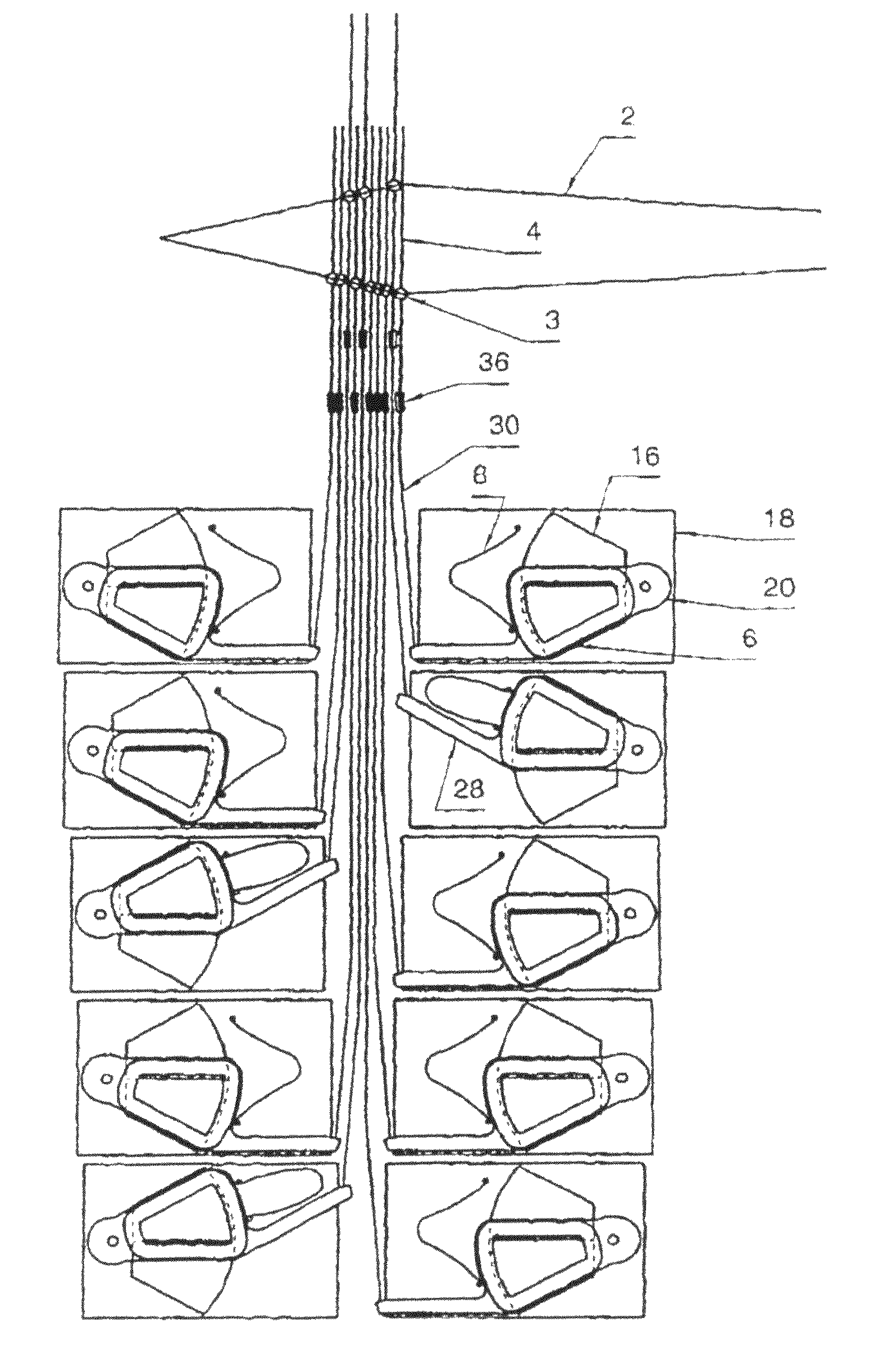
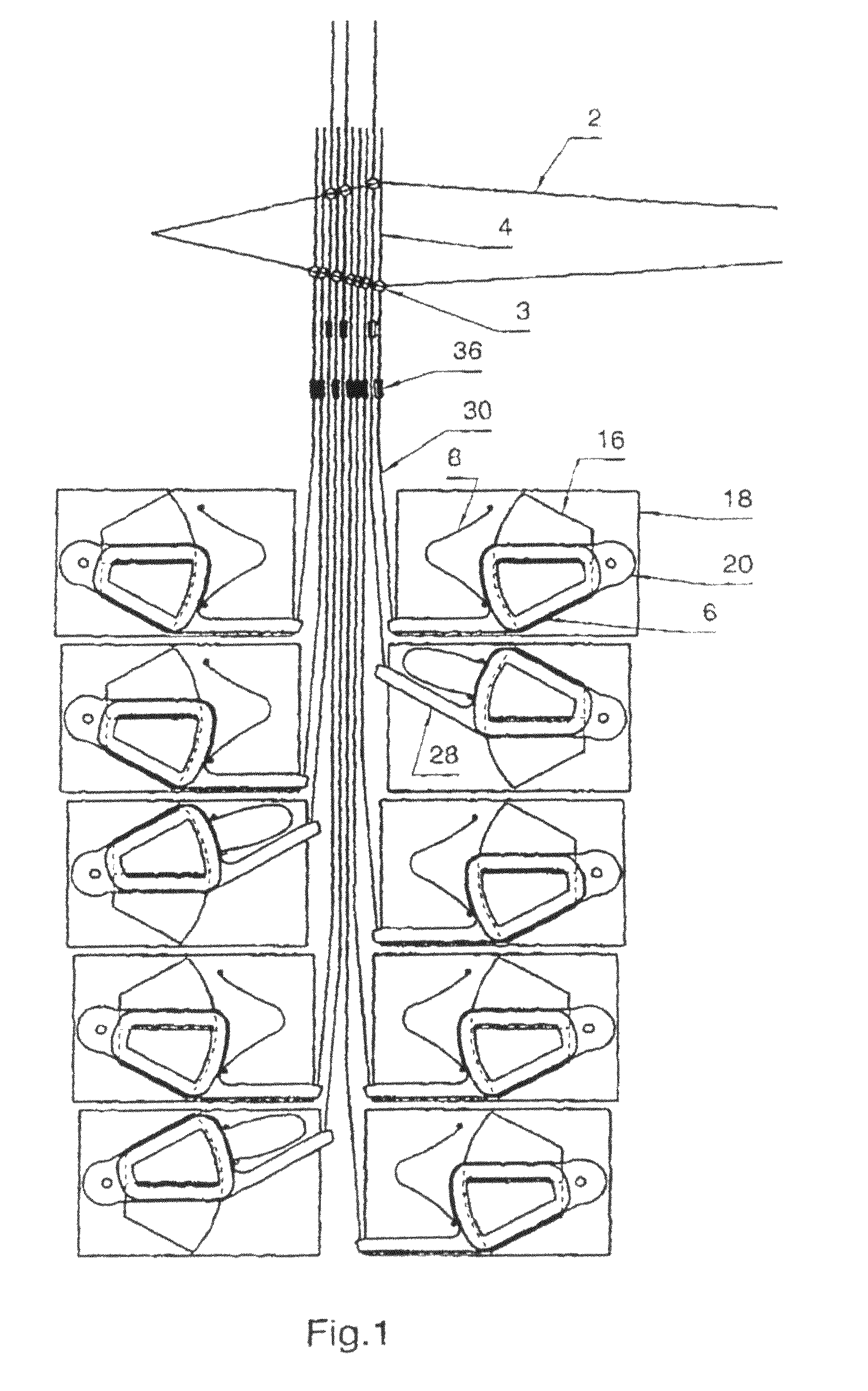
[0027]A first exemplary embodiment for carrying out the present invention is illustrated in FIGS. 1 and 2.

[0028]FIG. 1 shows a device for driving the heddles 4, designed as driving parts of the warp threads 2, of a textile weaving machine having individual heddle movement, in a side view. The warp threads 2 are moved by means of the heddles 4 having thread eyes 3, such that, as illustrated in the exemplary embodiment, they are located either in an upper shed position or in a lower shed position. The heddles 4 are arranged by means of couplings 36 on push and pull rods 30 which in each case have a length different from that of the adjacent rod. The drive elements for the heddles 4 can thereby be arranged in a staggered or register-like manner. The staggered or register-like arrangement is provided here in duplicate form, in such a way that the left half of the heddles 4 is assigned to a left register of electric motors 32 and the elements assigned to these, while the right half of th...


PUM


Abstract

In order to solve the problem of not having enough space available for a large number of components and keeping the deflection of the electric motor small in a device for controlling the transverse movement of the warp threads of a textile weaving machine, particularly a textile weaving machine with single strand movements, the invention proposes to operatively connect the strands via power transmission elements having different lengths in a staggered or register-like way to an electric motor and to provide the electric motors with a ratio in relation to the strands such that the movement of the electric motors brings about a greater movement of the strands.

Description

[0001]This application claims priority of PCT application PCT / CH2007 / 000559 having a priority date of Mar. 27, 2007, the disclosure of which is incorporated herein by reference.TECHNICAL FIELD[0002]The invention relates to a device for controlling the transverse movement of the warp threads of a textile weaving machine, in particular of a textile weaving machine having individual heddle movement.BACKGROUND OF THE INVENTION[0003]Devices for controlling the transverse movement of the warp threads of textile weaving machines, in particular of weaving machines having individual heddle movement, are basically known from numerous documents. In many of these publications, attempts are made to put forward suitable proposals so that the problematic weaving harness of a shedding device of a Jacquard machine can be dispensed with.[0004]EP 0 353 005 A1 discloses a drive arrangement for controlling the transverse movement of the warp threads, in which, with a linear motor, a closed drive cord fo...

Claims


Application Information

Patent Timeline
Patent Type & Authority Patents(United States)
IPC IPC(8): D03C3/20D03C3/32D03C5/06
CPCD03C13/00D03C3/20D03C3/205
Inventor BORER, SILVAN
Owner TEXTILMA AG
Why Eureka
Try Eureka