
Door hinge

Active Publication Date: 2010-06-17
FARINGOSI HINS R L
View PDF8 Cites 31 Cited by
  • Summary
  • Abstract
  • Description
  • Claims
  • Application Information

AI Technical Summary

Benefits of technology

[0019]The Applicant has found out that using a fluidically operated cylinder and piston of the type with internal flow leakage of the fluid, i.e. the fluid being induced to flow, with a certain resistance, from one chamber of the cylinder to the other, i.e. from the upstream to the downstream chamber, relative to the direction of the respective movement of the piston moving within the damper cylinder, allows accurately adjusting the resistance offered by the damper, at least in one forward direction of the piston within the cylinder, and thus slowly and continuously closing and / or opening the door and effectively preventing, both in the closing and opening steps, any impacts from occurring between the door and compartment structure, even when wrong manoeuvres are made by the user, such as applying an excessive closing / opening force, or unusual efforts on the door, etc.
[0021]Also in this case, using said movement guide means in combination with the fluidic damper of the type with internal flow leakage of the fluid allows obtaining a hinge that can be easily used by a user, which prevents any impacts from occurring between the door and the respective compartment structure, when the door is being closed or opened.
[0022]According to a preferred aspect of the present invention, said damper further comprises at least one region, within the cylinder, which offers a higher resistance to the relative movement, at least in one direction, of the piston, relative to other inner regions of the cylinder. In other words, in this higher-resistance region, preferably defined by the geometrical configuration of the cylinder and / or piston and / or ports of the internal flow leakage for the fluid, the speed, at least in one direction, of the piston results to be reduced, relative to the other cylinder regions, mainly due to the increased resistance against the passage between piston and cylinder walls and / or to the internal flow leakage of the fluid from one chamber to the other, as well as due to the increased pressure of the fluid not yet internally leaked, while the latter is being compressed by the piston. This high-resistance region can consist of a reduced-section cylindrical chamber, with which the damper cylinder is provided at one end thereof, within which a corresponding appendix is engaged, which is also of a reduced-section and provided on the sliding cylindrical body of the piston.

Problems solved by technology

These prior art hinges, though allowing a quite accurate adjustment of the movement of the door relative to the compartment, do not prevent the possible impacts of the door against the compartment structure, when the door reaches one of the end-of-travel positions thereof, particularly the compartment closure end-of-travel position.
For example, when the spring is configured to counteract the opening of the door, preferably by collapsing from the zero (rest) position thereof, when the door is being closed by the user, the thrust given by the spring extending onto the respective moving element of the hinge can impress a considerable speed to the rotation of the door relative to the compartment, thus consequently causing the door to impact against the compartment structure when closing.
Furthermore, this type of damper makes the resistance offered to the movement of the piston higher and higher, in the fluid-compression direction, as this piston reaches the expected end-of-travel position thereof, thus making operating the oven door for closing uncomfortable and unnatural to the user.

Method used


Image

  • Door hinge
  • Door hinge
  • Door hinge

Examples


Embodiment Construction

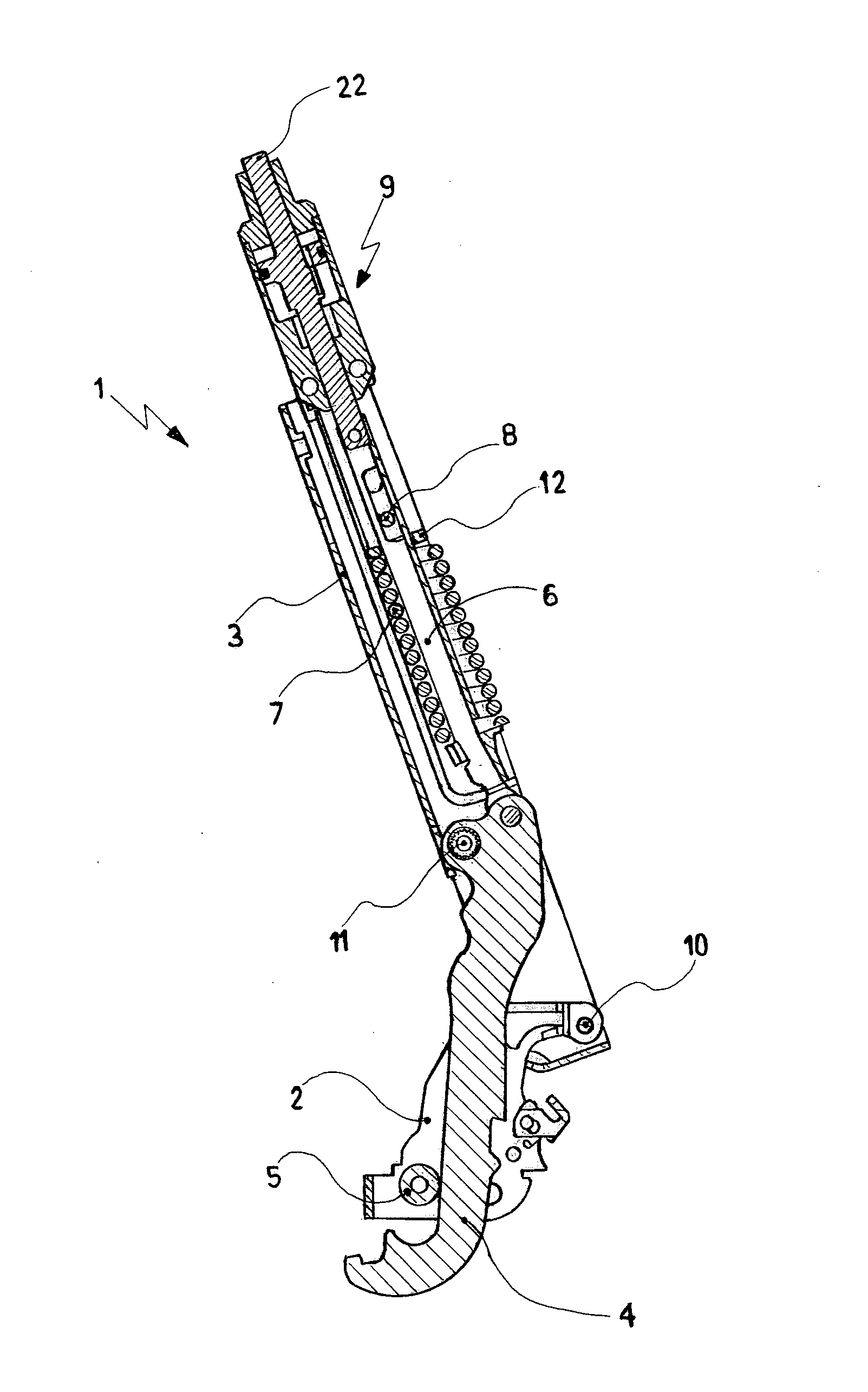
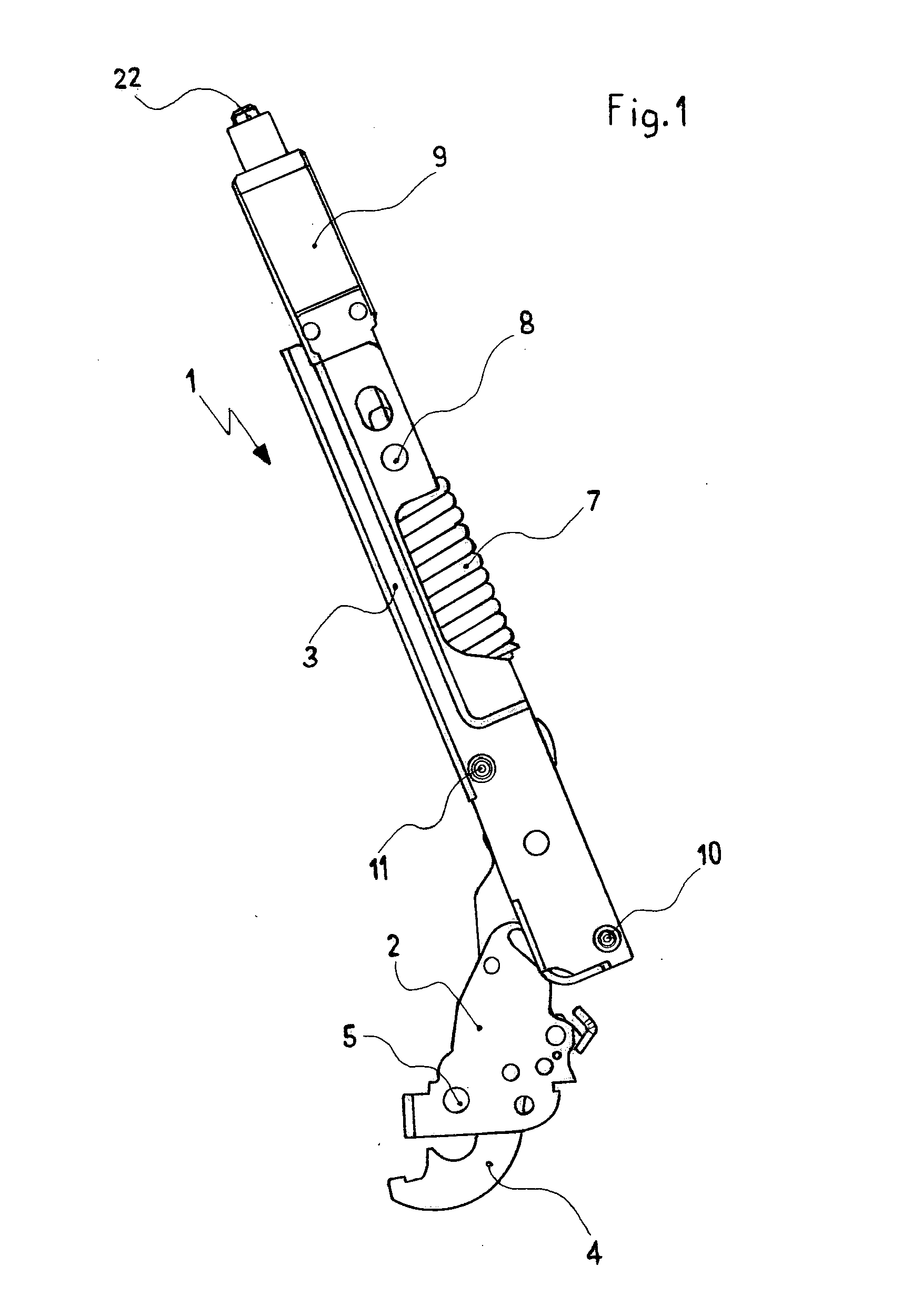
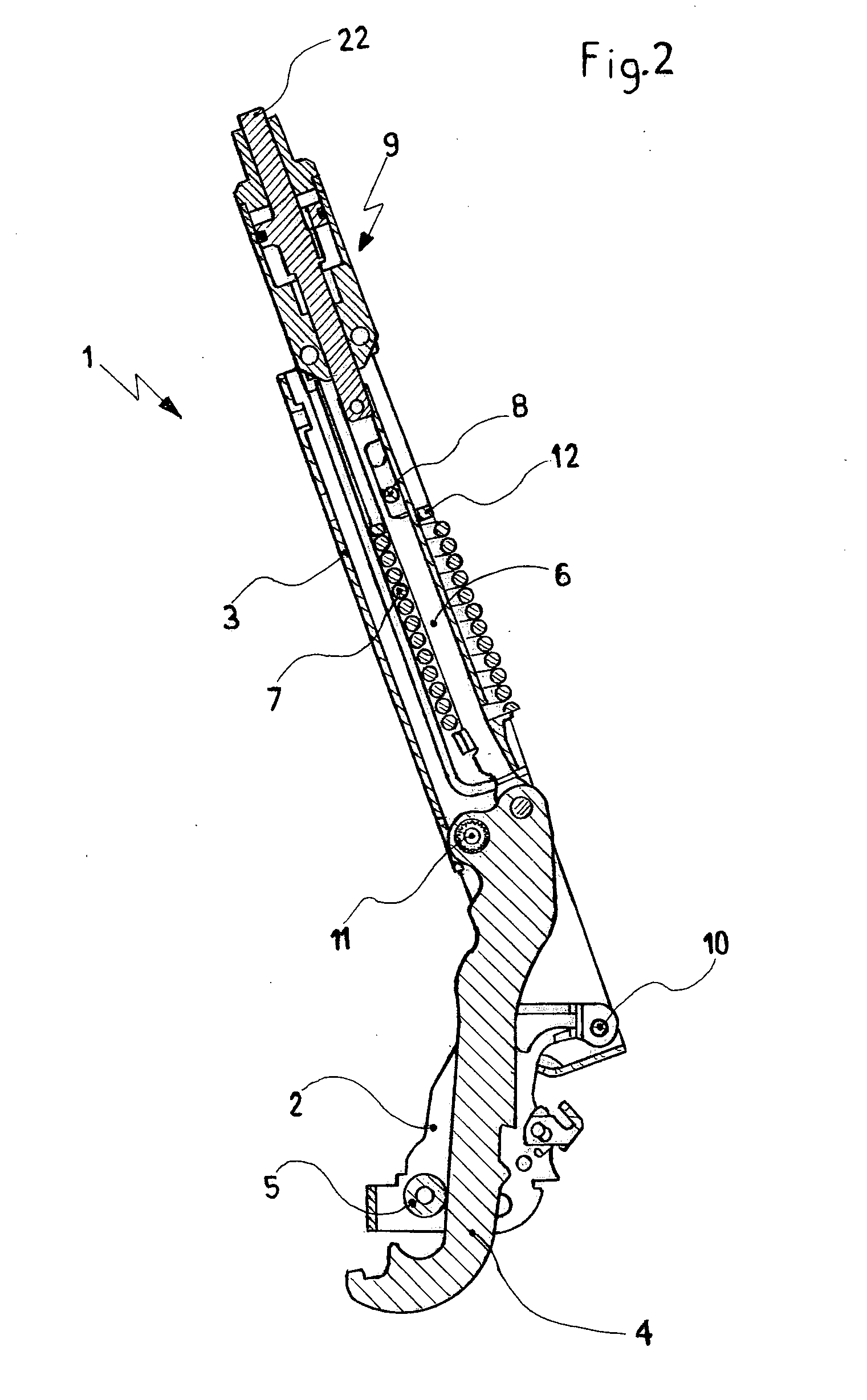
[0030]With reference to FIGS. 1 and 2, the hinge 1 for an oven door, according to a particular aspect of the present invention, comprises a first support, or articulation, 2, which is intended to be fixed to the outer structure of the compartment—or compartment—(not shown) of an oven and a second support, or base, 3, which is suitable to be fixed to the frame (also not shown) of a door covering the oven compartment. The first support 2 and second support 3 are hinged to each other, according to the prior art, by means of the pin 10, such that the support 3 is only rotatably constrained to support 2.

[0031]The hinge 1 also comprises, according to the prior art, guide means for the relative movement between these supports 2 and 3, and thus between oven door and compartment, of the type in which a moving arm, or sector, 4, which is suitably cam-like shaped, is constrained to the second support 3 and engages with an abutment, or follower, consisting of an idle wheel 5 mounted to the firs...


PUM


Abstract

A hinge (1) for a door opening over a horizontal axis, of the type comprising first and second supports (2, 3) that can be fixed to a compartment structure and to a door, at least rotatably constrained to each other through a pin (10). The hinge (1) comprises a fluidic cylinder-piston damper (9) of the type with internal flow leakage of the fluid contained therein. The damper (9) has a piston (18, 19) with a through-hole (20). The piston (18, 19) can have an appendix (19) that non-sealingly engages a chamber (17) when the door is closed, to increase the dampening. The hinge (1) has elastic means (7) such as a spring, to counteract the falling movement of the door when it is opened. The hinge (1) can be of the cam type, with a cam (4) and an abutment (5).

Description

FIELD OF THE INVENTION[0001]The present invention relates to a hinge for compartment-covering doors, such as those suitable to close an oven compartment, of the type in which the law of motion governing the relative movement of two supports hinged to each other, and respectively fixed to the compartment and door structure, or vice versa, are given by movement guide means, preferably of the cam-follower type, which are interposed between, and operatively connected to, both of the two supports.BACKGROUND OF THE ART[0002]It is known to provide such type of hinges in which these movement guide means comprise an arm, usually cam-shaped, which is constrained as a rocker arm to one of said hinge supports, such that the one end thereof defines the sliding movement of a moving element relative to the support to which it is constrained, and the other end of the arm, suitably shaped, is instead engaged with an abutment, or follower, which is preferably an idle wheel, mounted to the other hinge...

Claims


Application Information

Patent Timeline
IPC IPC(8): A47B96/00E05F1/08
CPCE05F1/1261Y10T16/5383E05F5/10E05Y2201/21E05Y2201/256E05Y2201/264E05Y2900/308F16F9/3214F16F9/49F24C15/023E05F5/02Y10T16/2771Y10T16/304Y10T16/538E05F3/22E05F1/12F16F9/02F16F9/20F24C15/02
Inventor BETTINZOLI, ANGELO
Owner FARINGOSI HINS R L
Learn More