Light guide structure for a keyboard

a technology of light guide structure and keyboard, which is applied in the direction of keyboard-like device coding, pulse technique, coding, etc., can solve the problems of increasing complexity in circuit design, obstructing the path of light, and structure, so as to avoid shadow, improve the uniformity of backlight illumination of the press keys, and avoid the effect of insufficient backlight brightness

Inactive Publication Date: 2010-06-17
KINPO ELECTRONICS
View PDF3 Cites 29 Cited by
  • Summary
  • Abstract
  • Description
  • Claims
  • Application Information

AI Technical Summary

Benefits of technology

[0009]It is therefore a primary object of the present invention to provide alight guide structure for a keyboard, which is able to enhance uniform backlight illumination of the press keys and peripheries thereof and avoid shadow caused by insufficient backlight brightness.
[0010]It is a further object of the present invention to provide the above light guide structure for the keyboard, which is able to promote utility efficiency of light and lower power consumption.
[0014]At least one light reflection layer is disposed under a bottom face of an abutment unit of the top side of the resilient support section. At least one carbon paste layer is disposed under a bottom face of the light reflection layer. Accordingly, the light reflection layer is able to reflect light toward the press key, which light comes from a light guide plate or from other light sources. Therefore, the light guide structure is able to enhance reuse efficiency of the light and avoid the shadow caused by the carbon paste layer.

Problems solved by technology

Such structure will obviously obstruct the path of the light guided by the light guide element 5.
This directly leads to increment of manufacturing cost.
This also increases complicatedness in circuit design and results in higher power consumption.
Apparently, such structure is not economic.
Therefore, the light coming from the light guide elements or the light source will be again and again reflected to the periphery of the press key and lost.
The randomly scattered light is not fully utilized so that the illumination provided by the backlight module can be hardly enhanced.
Therefore, a shadow is often produced at the center of the press key due to insufficient backlight.

Method used


Image

  • Light guide structure for a keyboard
  • Light guide structure for a keyboard
  • Light guide structure for a keyboard

Examples


Embodiment Construction

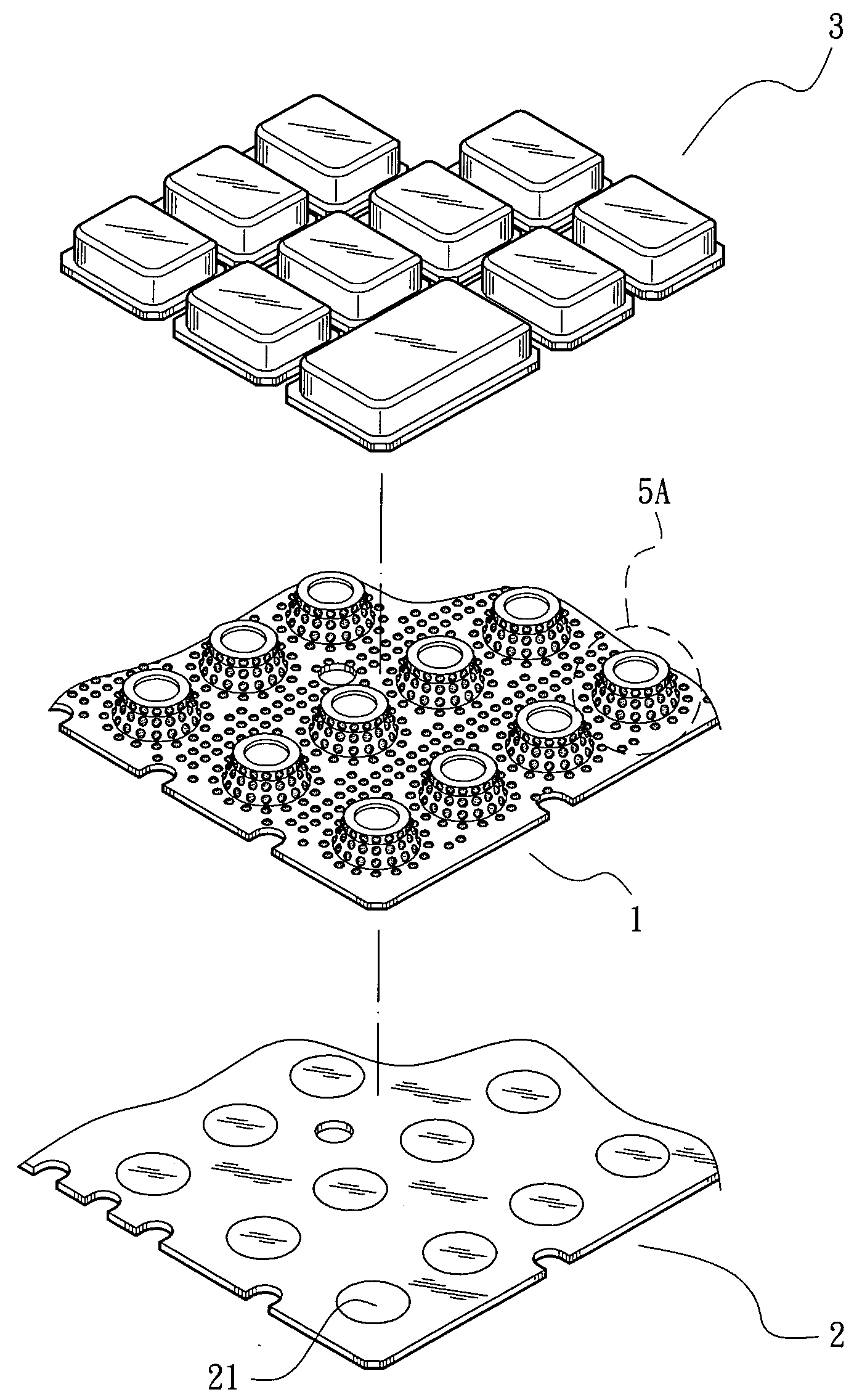
[0032]Please refer to FIGS. 5 to 7. According to a first embodiment of the present invention, at least one bell-shaped raised resilient support section 11 is formed on a rubber sheet 1 in alignment with a press key 3. An abutment unit 12 is disposed on a top side of the resilient support section 11. A top face of the abutment unit 12 is positioned right under a bottom face of the press key 3 or in contact with the bottom face of the press key 3. An electric contact section 13 (such as a carbon paste contact) is disposed under a bottom face of the abutment unit 12. At least one diffusive reflection unit 15 is disposed on a surface of the rubber sheet 1 and at least a part of outer circumference of the resilient support section 11. In this embodiment, the diffusive reflection unit 15 is a boss section, a convex section or a dome section protruding from the surface of the rubber sheet 1. The diffusive reflection unit 15 has a surface coated with a light reflection layer 151 for reflect...


PUM


Abstract

A light guide structure for a keyboard. The light guide structure includes a transparent rubber sheet. Multiple resilient support sections are formed on the rubber sheet in alignment with press keys of the keyboard respectively. Multiple diffusive reflection units are disposed on a surface of the rubber sheet and circumferences of the resilient support sections. The diffusive reflection units are boss sections protruding from the surface of the rubber sheet or recessed sections formed on the surface of the rubber sheet. Each diffusive reflection unit has a surface coated with a light reflection layer for reflecting light. When the light is reflected by external components back to the surface of the rubber sheet, the light reflection layers of the diffusive reflection units that are boss sections or recessed sections will again effectively reflect the light to enhance backlight brightness of the press keys and peripheries thereof.

Description

BACKGROUND OF THE INVENTION[0001]The present invention is related to a light guide structure for a keyboard, and more particularly to a rubber sheet light guide structure, which is able to enhance backlight brightness of press keys of the keyboard and promote reuse efficiency of light.[0002]FIG. 1 shows a backlight structure applied to a press key of an electronic product. The backlight structure includes a nontransparent press key 51, a light guide element 5 and a light-emitting element 52. The light-emitting element 52 is arranged on a backside of the press key 51. The light emitted from the light-emitting element 52 is guided by the light guide element 5 around the press key 51 and projected to a front side of the press key 51. By means of the arrangement of the light guide element 5 and the light-emitting element 52, the light can be uniformly distributed over a periphery of the press key 51 without local bright spot.[0003]According to the above arrangement, the light emitted fr...

Claims


Application Information

Patent Timeline
Patent Type & Authority Applications(United States)
IPC IPC(8): H03M11/00
CPCH01H13/83H01H2209/082H01H2219/062H01H2219/056H01H2219/06H01H2219/044
Inventor WANG, CHIEN-LUNG
Owner KINPO ELECTRONICS
Why Eureka
Try Eureka