Multi band built-in antenna

a built-in antenna and antenna technology, applied in the structural form of resonant antennas, elongated active elements, radiating elements, etc., can solve the problems of increasing manufacturing costs, processing costs, increasing the number of components, etc., and achieves the effect of reducing manufacturing costs, simplifying the antenna structure, and easy tuning of antenna characteristics

Active Publication Date: 2010-06-17
ACE ANTENNA
View PDF9 Cites 10 Cited by
  • Summary
  • Abstract
  • Description
  • Claims
  • Application Information

AI Technical Summary

Benefits of technology

[0018]The present invention has advantages in that a ground clip is formed to fasten a transmission line and a main board, so that signals are grounded, the transmission line is supported, and easy tuning of antenna characteristics is enabled. A radiator is formed to include the dielectric and the central conductor of the transmission line, other than the external conductor of the transmission line, in case that the transmission line includes the external conductor, the dielectric, and the central conductor, so that the structure of the antenna is simplified. The configuration of an antenna is formed by a ground clip and a radiator using a transmission line, so that the manufacturing cost decreases.
[0019]The present invention has an advantage in that an open stub is formed on a ground clip for grounding a main board and a transmission line, and the open stub is operated together with a radiator formed by the dielectric and the central conductor of the transmission line, without the external conductor of the transmission line, so that the resonance characteristics of a low frequency band are further improved, thereby obtaining broadband characteristics.

Problems solved by technology

This causes problems in that the manufacturing cost increases due to the increase in the processing cost and the increase in the number of components, and the structure of an antenna is complex.

Method used


Image

  • Multi band built-in antenna
  • Multi band built-in antenna
  • Multi band built-in antenna

Examples


Embodiment Construction

[0036]Preferred embodiments of the present invention will be described in detail with reference to the attached drawings below.

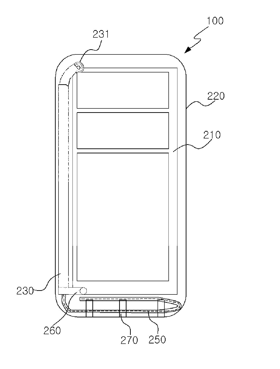
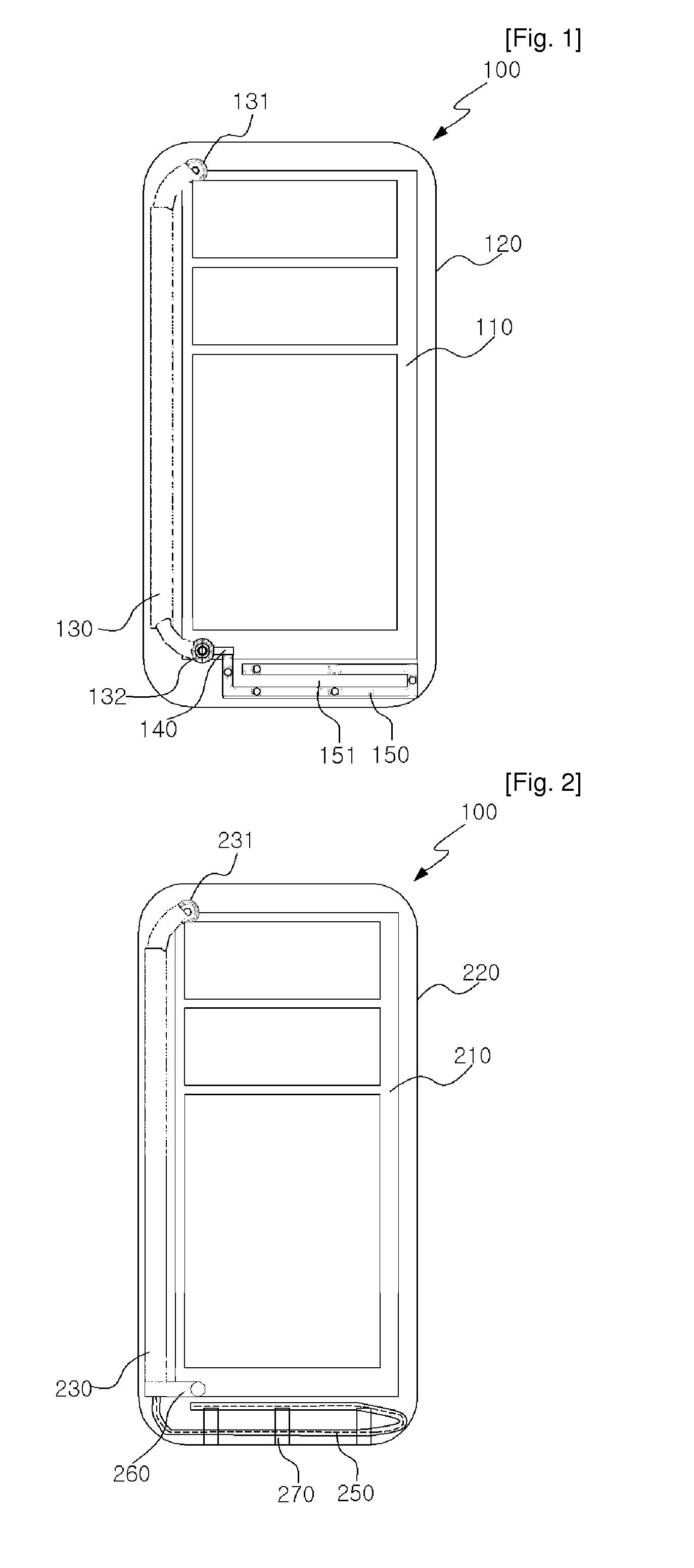
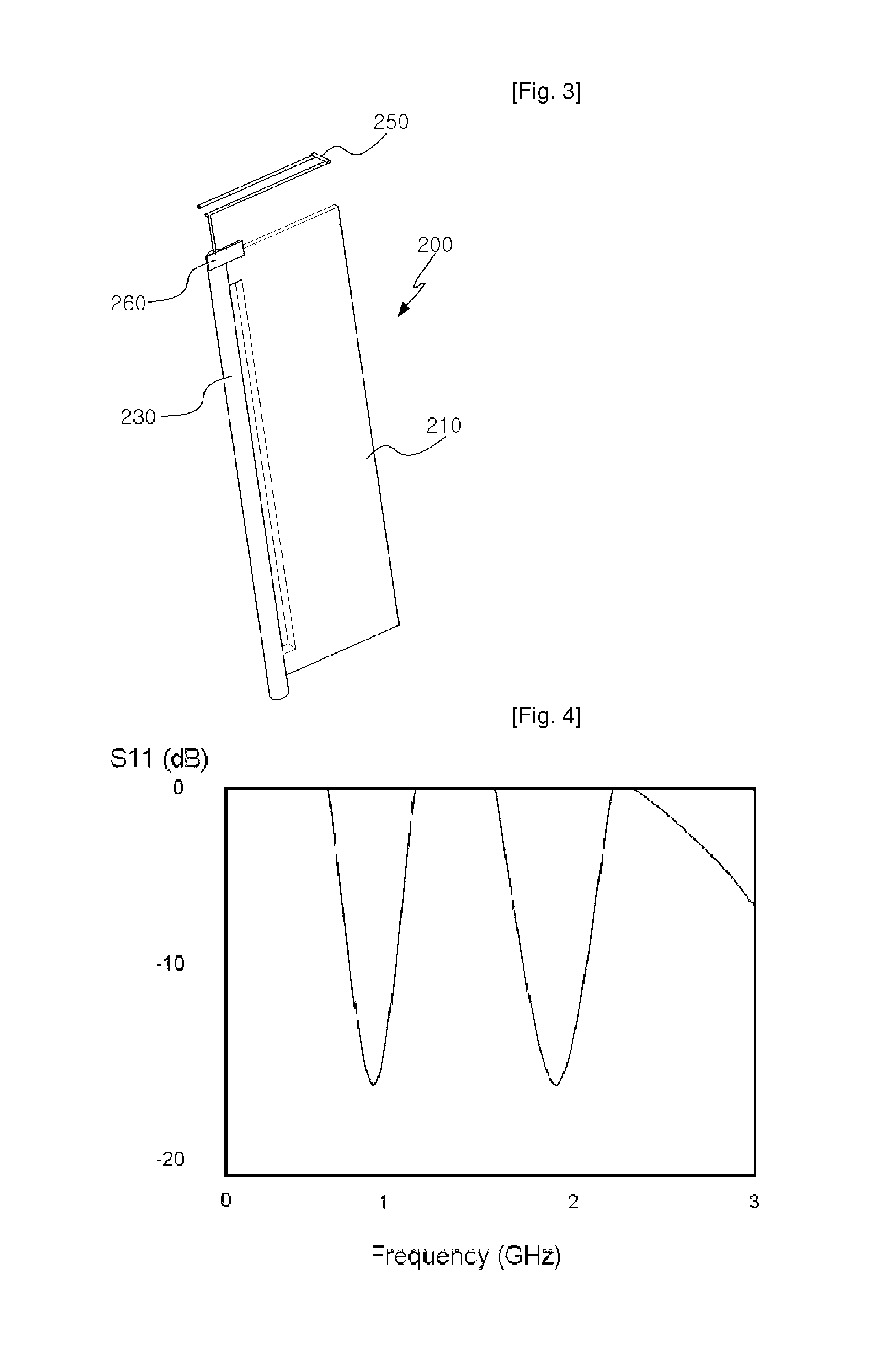
[0037]FIG. 2 is a view showing the configuration of a multi-band built-in antenna according to an embodiment of the present invention, and FIG. 3 is a perspective view showing the multi-band built-in antenna of FIG. 2 according to the present invention. In a mobile communication terminal 200 including a main board 210 and a casing 220 for protecting the main board 210, the multi-band built-in antenna includes a transmission line 230, formed to be spaced apart from the outside surface of the main board 210 by a predetermined interval and configured to include an external conductor, a dielectric, and a central conductor so as to transmit signals, and a radiator 250 formed by bending the dielectric and central conductor of the transmission line 230, without the external conductor of the transmission line 230 and configured to operate in multiple bands.

[0038]Fur...


PUM


Abstract

A multi-band built-in antenna for a mobile communication terminal having a main board and a casing for protecting the main board, is disclosed. A transmission line is formed to be spaced apart from one outside surface of the main board by a predetermined interval and configured to include an external conductor, a dielectric, and a central conductor so as to transmit signals. A ground clip is configured to ground the transmission line by fastening the transmission line. A radiator is formed by bending the dielectric and central conductor of the transmission line, other than the external conductor of the transmission line, and is configured to operate in multiple bands. An open stub is connected to the ground clip, is bent a plurality of times, and is configured to be operated in a low frequency band, which is lower than the high frequency band.

Description

TECHNICAL FIELD [0001]multi-band built-in antenna,multi-band built-in antenna which operates in multiple bands by using one end of a transmission line, including an external conductor, a dielectric and a central conductor, as a radiator. This enables easy tuning of antenna characteristics by fastening the transmission line and the main board of a mobile communication terminal using a ground clip, and which enables tuning of antenna characteristics by changing the structure or shape of the ground clip.BACKGROUND ART [0002]A prior art built-in antenna is a technology in which, in a mobile communication terminal 100 including a main board 110 and a casing 120, a coaxial line 130 for transmitting signals is formed, a forward connector 131 for a coaxial line is formed on one end of the coaxial line 130 and a backward connector 132 for a coaxial line 130 is formed on the other end of the coaxial line 130, a feed line 140 is formed on the backward connector 132 for a coaxial line, and a me...

Claims


Application Information

Patent Timeline
Patent Type & Authority Applications(United States)
IPC IPC(8): H01Q5/00H01Q9/04H01Q1/00H01Q5/357H01Q5/378
CPCH01Q1/243H01Q1/36H01Q9/22H01Q5/378H01Q9/38H01Q9/42H01Q5/357H01Q9/26H01Q1/24H01Q5/00
Inventor KIM, BYONG-NAM
Owner ACE ANTENNA
Why Eureka
Try Eureka