Method for implementing mouse algorithm using tactile sensor

Inactive Publication Date: 2010-06-17
KOREA RES INST OF STANDARDS & SCI
View PDF5 Cites 88 Cited by
  • Summary
  • Abstract
  • Description
  • Claims
  • Application Information

AI Technical Summary

Problems solved by technology

Here, the button and switch are generally mechanical, so that they have the disadvantage of being limited in being controlled to move the cursor or make selections.
As a result, it is difficult to apply the conventional mouse using the position recognition to a mobile devic

Method used


Image

  • Method for implementing mouse algorithm using tactile sensor
  • Method for implementing mouse algorithm using tactile sensor
  • Method for implementing mouse algorithm using tactile sensor

Examples


first embodiment

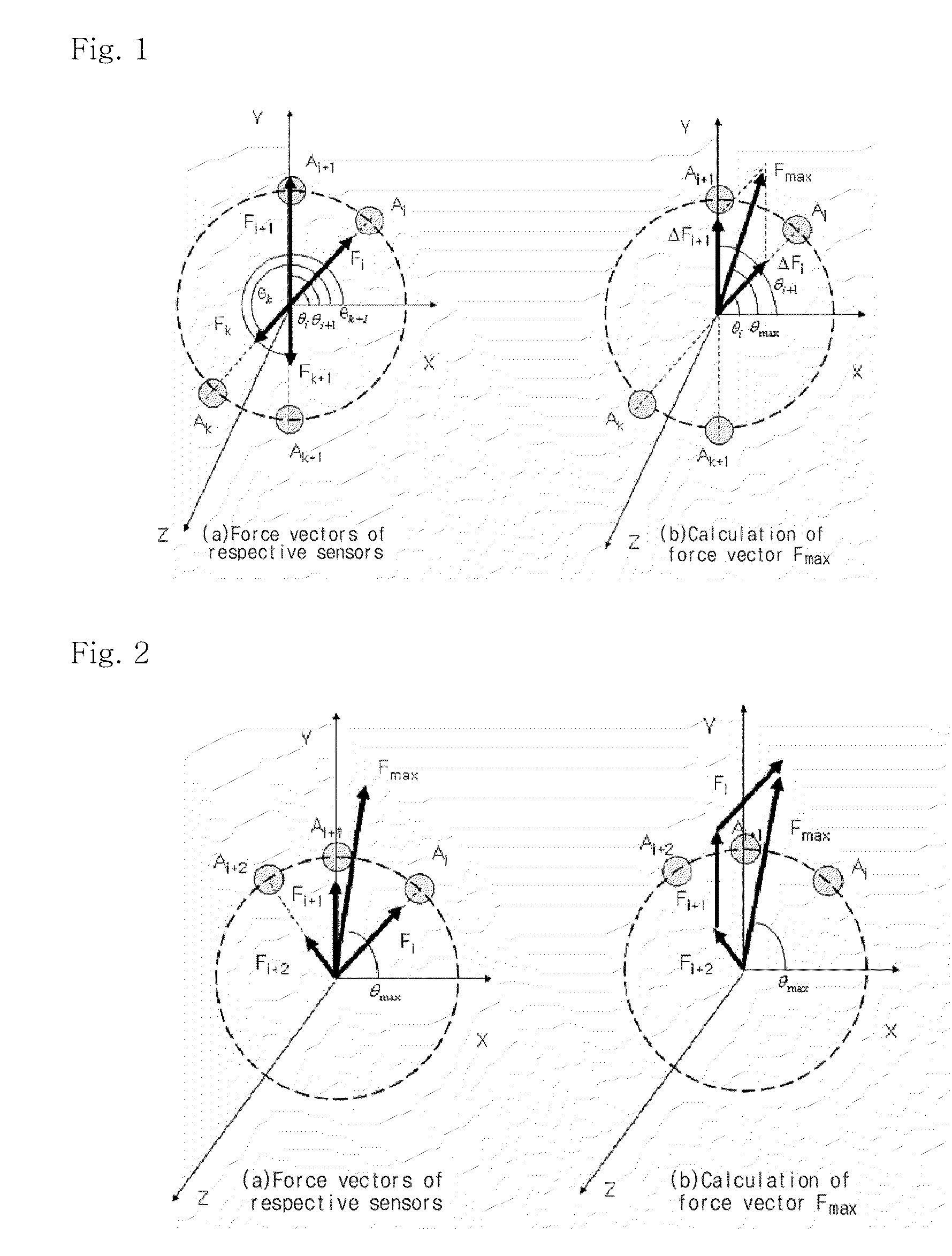
[0032]the present invention will hereinafter be described with reference to FIGS. 1A and 1B. First, as shown in FIG. 1A, force vectors Fi, Fi+1, Fk and Fk+1 having magnitudes |Fi|, |Fi+1|, |Fk| and |Fk+1| and X-axis angles θi, θi+1, θk and θk+1are obtained from arbitrary sensors Ai, Ai+1, Ak and Ak+1 representing the outputs of force, among the plurality of pressure sensors, respectively.

[0033]Then, the X-axis angles θi and θi+1 and magnitudes |Fi−Fk| and |Fi+1−Fk+1| of force vectors ΔFi and ΔFi+1 are calculated using the force vectors Fi, Fk, Fi+1 and Fk+1, as shown in FIG. 1B.

[0034]Then, a force vector Fmax of the contact point having an X-axis angle θmax and a magnitude |Fmax| is calculated using the X-axis angles θi and θi+1 and magnitudes |Fi−Fk| and |Fi+1−Fk+1| of the vectors ΔFi and ΔFi+1, and the moving distance and direction of a mouse cursor are sensed from the calculated force vector Fmax.

[0035]Here, the moving distance of the mouse cursor may be calculated based on the m...

second embodiment

[0036]the present invention will hereinafter be described with reference to FIGS. 2A and 2B. First, a force vector Fi+1 of an (i+1)th sensor Ai+1 having a maximum magnitude of force, among a plurality of pressure sensors around the contact point, and force vectors Fi and Fi+2 of an ith sensor Ai and (i+2)th sensor Ai+2 located at both sides of the (i+1)th sensor Ai+1 are found as shown in FIG. 2A.

[0037]Then, a force vector Fmax having the sum |Fmax| of the magnitudes of the force vectors Fi+1, Fi and Fi+2 of the (i+1)th sensor Ai+1, ith sensor Ai and (i+2)th sensor Ai+2 and an X-axis angle θmax is calculated as shown in FIG. 2B.

[0038]Then, the moving distance and direction of a mouse cursor are calculated using the force vector Fmax. Here, the moving distance of the mouse cursor may be calculated based on the magnitude sum |Fmax| and the moving direction of the mouse cursor may be calculated based on the X-axis angle θmax, or the magnitude sum |Fmax| may be defined as |Fmax|cosθmax+...

third embodiment

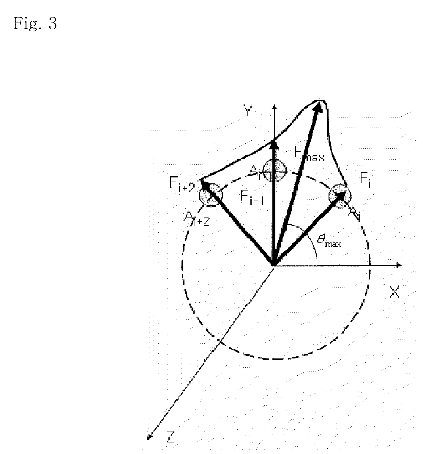
[0039]Referring to FIG. 3, in the present invention, a force vector Fi+1 of an (i+1)th sensor Ai+1 having a maximum magnitude of force, among a plurality of pressure sensors around the contact point, and force vectors Fi and Fi+2 of an ith sensor Ai and (i+2)th sensor Ai+2 located at both sides of the (i+1)th sensor Ai+1 are found.

[0040]Then, a magnitude distribution function F(θ)=aθ+a1θ+a2θ2 is obtained by fitting force magnitudes |Fi|, |Fi+1| and |Fi+2| corresponding respectively to the coordinates of the ith sensor Ai, (i+1)th sensor Ai+1 and (i+2)th sensor Ai+2 to a quadratic curve.

[0041]Then, an X-axis angle θmax where the maximum force magnitude is present is obtained, a force vector Fmax having a maximum magnitude |Fmax| at the angle θmax is obtained from the magnitude distribution function, and the moving distance and direction of a mouse cursor are calculated using the obtained force vector Fmax.

[0042]Here, the moving distance of the mouse cursor may be calculated based on ...


PUM


Abstract

A method for implementing a mouse algorithm using a plurality of pressure sensors is disclosed. The pressure sensors are used to freely move and rotate a mouse cursor in X, Y and Z directions, so that they can be applied as interface units for a slim device such as a mobile phone. The mouse algorithm processes a touch input. The pressure sensors are arranged in a ring shape and provide output values successively varying with magnitudes of forces applied thereto or pressures applied thereto. A moving direction of the mouse cursor is determined depending on a contact point detected through the output values and a moving distance and moving speed of the mouse cursor are determined in proportion to the magnitudes of the forces.

Description

BACKGROUND OF THE INVENTION[0001]1. Field of the Invention[0002]The present invention relates to a mouse algorithm implementation method, and more particularly to a method for implementing a mouse algorithm using a plurality of pressure sensors, in which the pressure sensors are used to freely move and rotate a mouse cursor in X, Y and Z directions, so that they can be applied as interface units for a slim device such as a mobile phone.[0003]2. Description of the Related Art[0004]Nowadays, in computer systems, there are various types of input units that perform input operations. These operations generally correspond to selections on a display screen by the movement of a cursor, and include a page turning function, scroll function, panning function, zooming function, etc.[0005]In general, the input units include a button, switch, keyboard, mouse, trackball, joystick, etc.[0006]Here, the button and switch are generally mechanical, so that they have the disadvantage of being limited in...

Claims


Application Information

Patent Timeline
IPC IPC(8): G06F3/041
CPCG06F3/0416G06F3/0414G06F3/0346G06F3/0354
Inventor KIM, JONG-HOKWON, HYUN-JOONPARK, YON-KYUKIM, MIN-SEOKKANG, DAE-IMCHOI, JAE-HYUK
Owner KOREA RES INST OF STANDARDS & SCI
Why Eureka
Try Eureka