Optical tactile sensor having a transparent elastic tactile portion

a tactile sensor and optical technology, applied in the field of optical tactile sensors, can solve the problems of inability to determine whether the force is perpendicular to the surface, acting horizontally, or unable to solve the lack of a solution

Inactive Publication Date: 2005-06-21
TOUDAITLO LTD
View PDF9 Cites 61 Cited by
  • Summary
  • Abstract
  • Description
  • Claims
  • Application Information

AI Technical Summary

Benefits of technology

[0005]The present invention has been conceived to resolve the problems mentioned, and provides an optical tactile sensor provided with a tactile section and imaging means, the tactile section comprising a transparent elastic body and a plurality of groups of markers provided inside the elastic body, each marker group being made up of a number of colored markers, with markers making up different marker groups having different colors for each group, and behavior of the colored markers when an object touches the elastic body being photographed by the imaging means. At least one of displacement, strain and inclination of the colored markers when the elastic body is touched by a body is observed by photographing behavior of the colored markers. Strain information inside the transparent elastic body is detected from information about the colored markers when a contact object touches the sensor, and the shape of the contact object calculated from strain information, and information about force acting on a contact interface (including both the elastic body surface and the contact object surface) are also detected. According to the present invention, it is possible to separately collect a plurality of types of information with a simple method called “color coding”, and it is possible to acquire a plurality of types of tactile information at the same time with an optical system. According to the present invention an unknown number or more of independent observed values are collected using color coding, and it is possible to estimate and reconstruct force vectors by stably resolving a reverse problem.

Problems solved by technology

However, a lot of surface type tactile sensors that are presently being used only acquire information for at best one degree of freedom for each point of the contact surface, as in cases where, for example, conductive rubber is used.
Therefore, even if it is possible to ascertain the condition of a force generally acting and its distribution, it is difficult to determine whether this force is perpendicular to the surface, for example, or acting horizontally.
With this method, however, in a lot of instances this information has upward or downward displacement or pressure and the previously described problem where information is lacking is not resolved.

Method used


Image

  • Optical tactile sensor having a transparent elastic tactile portion
  • Optical tactile sensor having a transparent elastic tactile portion
  • Optical tactile sensor having a transparent elastic tactile portion

Examples


first embodiment

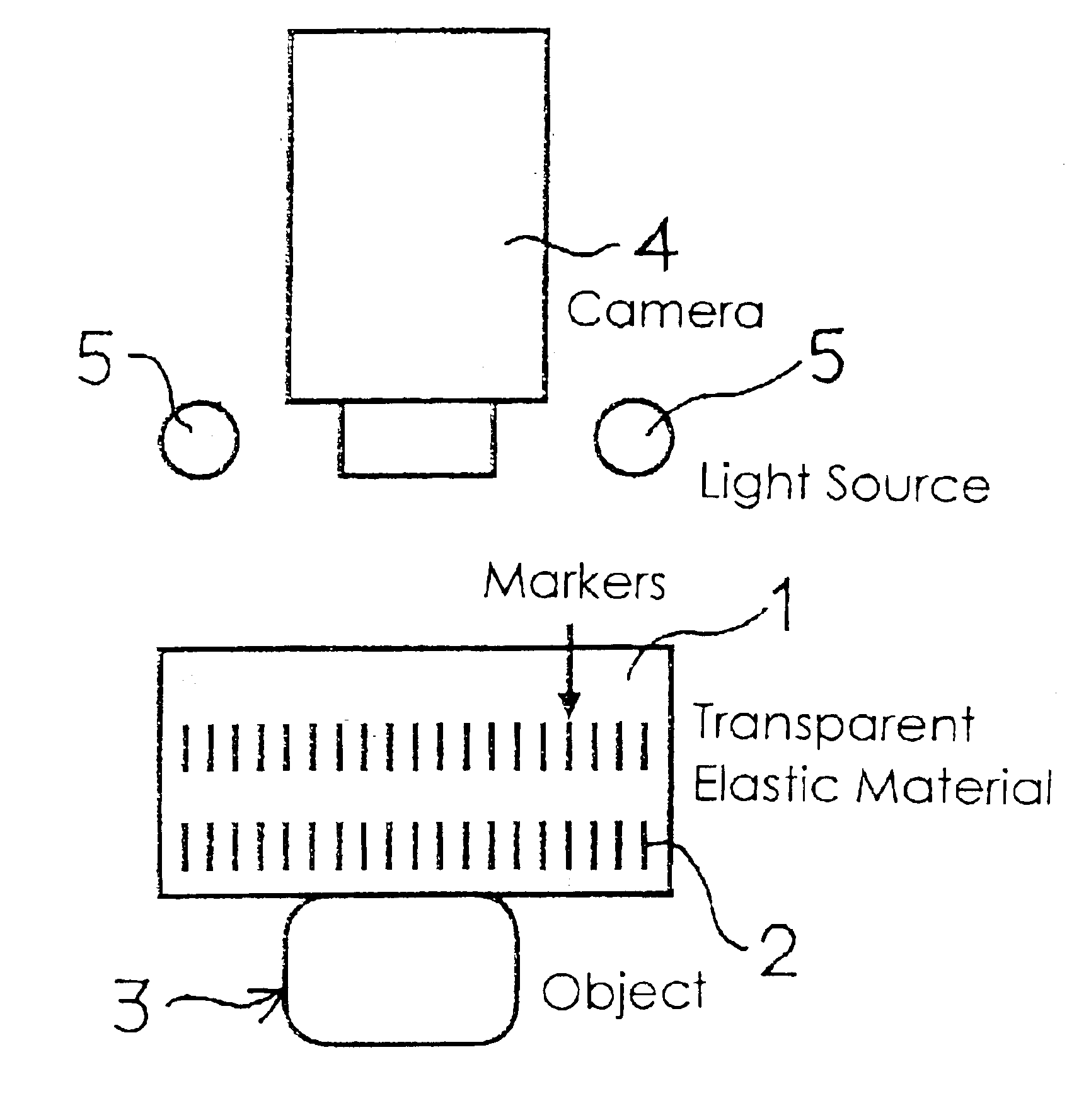
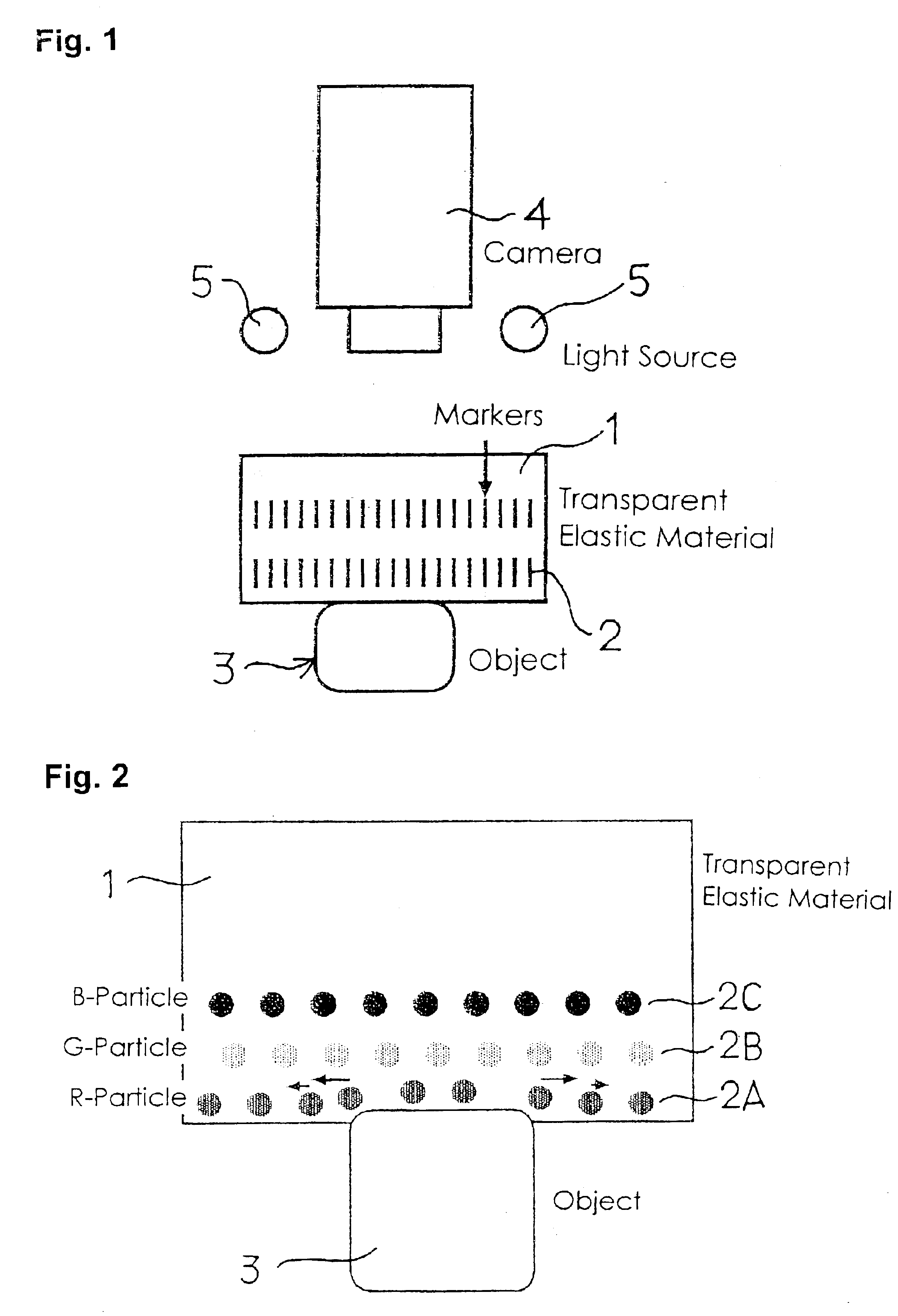
[0037]The first embodiment has spherical markers arranged in a depth direction. As shown in FIG. 2, microscopic colored spherical particles are used as the markers, and these are distributed separately in a plurality of layers according to color. For example, if they are divided into RGB (red, green and blue), these are simple to perceive by separating for each layer using color filters of a camera. With the arrangement shown in the drawing, a marker group 2A made up of red microscopic spherical markers is embedded in the shallowest section (the side distance from the camera) from a surface of the transparent elastic body 1 that an object 3 comes into contact with, a marker group 2B made up of green microscopic spherical markers is embedded in a section that is deeper than the layer marker group 2A is embedded in, and a marker group 2C made up of blue microscopic spherical markers is embedded in a section that is deeper than the layer marker group 2B is embedded in (the side close t...

second embodiment

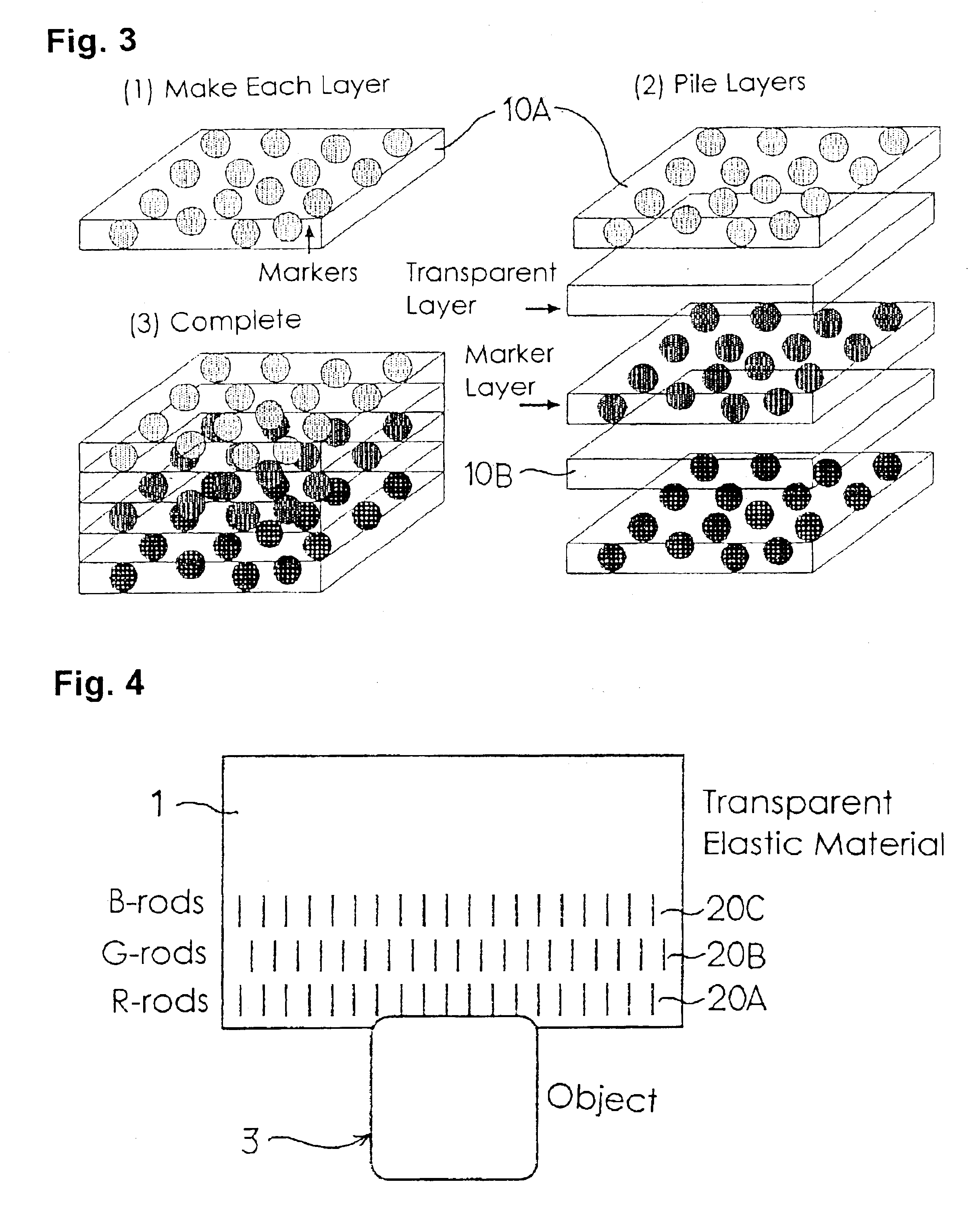
[0045]A second embodiment of the present invention will now be described based on FIG. 4 and FIG. 5. With the second embodiment, markers are extremely thin cylinders or columns having microscopic cross sections and in the drawings the markers are embedded vertically inside a transparent elastic body. The markers extend along imaginary lines connecting an object coming into contact with the elastic body and a camera. A marker group is formed in an elastic body 2 by providing a large number of markers in rows at a specified depth, with markers being provided in three stages at differing depths. In the drawings, a marker group 20A made up of extremely thin red cylindrical markers is embedded in the shallowest section from a surface of the elastic body 1 that an object 3 comes into contact with, a marker group 20B made up of extremely thin green cylindrical markers is embedded in a section that is deeper than the layer marker group 20A is embedded in, and a marker group 20C made up of e...

third embodiment

[0051]A third embodiment of the present invention will now be described based on FIG. 7. Extremely thin strips are used as the markers (for example, about 0.001 mm), and a large number of strips are aligned in parallel to constitute a marker group. Also, other color codes marker groups are aligned at a different angle to the first marker group. In the drawing, as one preferred aspect, two marker groups 200A (marker group comprising a plurality of thin red strips arranged in a row) and 200B (marker group comprising a plurality of thin blue strips arranged in a row) are aligned so that respective markers are orthogonal to each other, but the spatial arrangement relationship between the plurality of marker groups is not limited. It is also possible for the two sides of the strips constituting the marker to have different colors.

[0052]The strip shaped markers are embedded inside a rectangular parallelepiped shaped transparent elastic body 1 having a specified thickness. The strip shaped...


PUM

PropertyMeasurementUnit
diameteraaaaaaaaaa
diameteraaaaaaaaaa
thicknessesaaaaaaaaaa

Abstract

The invention relates to a tactile sensor capable of obtaining information for a plurality of degrees of freedom at each point on a surface by introducing multi-channel sensing that uses color or optical spectrum to an optical tactile sensor. An optical tactile sensor is provided with a tactile section and imaging means, the tactile section comprising a transparent elastic body and a plurality of groups of markers provided inside the elastic body, each marker group being made up of a number of colored markers, with markers making up different marker groups having different colors for each group, and behavior of the colored markers when an object touches the elastic body being photographed by the imaging means. Preferably, the marker groups have mutually different spatial arrangements.

Description

TECHNICAL FIELD[0001]The present invention relates to an optical tactile sensor, and preferably to a tactile sensor used for a robot hand.BACKGROUND ART[0002]When considering understanding the contact state of a contact surface using a tactile sensor, there are vectors of three components representing size and direction of force acting at each point of the contact surface. This is represented as f(x,y) in the coordinate system of FIG. 10. However, f is a vector, and so actually has three components x, y and z at each point. When explicitly expressing each component, it is represented as f(x,y)=[fx(x,y), fy(x,y), fz(x,y)].[0003]Since force distribution has three components at each contact point, in order to reconstitute force distribution of a contact surface using a tactile sensor it is necessary to acquire information for each contact point on the contact surface with at least three degrees of freedom. However, a lot of surface type tactile sensors that are presently being used onl...

Claims


Application Information

Patent Timeline
Patent Type & Authority Patents(United States)
IPC IPC(8): G01L5/22G01L1/24G01B11/03G01B11/06G01D21/00G06F3/033G06F3/042
CPCG01L1/247G06F3/0425G06F3/042G01L1/24
Inventor TACHI, SUSUMUKAJIMOTO, HIROYUKI
Owner TOUDAITLO LTD
Why Eureka
Try Eureka