Fixing device and image forming apparatus provided with the fixing device

Active Publication Date: 2010-06-17
KONICA MINOLTA BUSINESS TECH INC
View PDF8 Cites 9 Cited by
  • Summary
  • Abstract
  • Description
  • Claims
  • Application Information

AI Technical Summary

Benefits of technology

[0019]The present invention has been achieved in view of the above problem and aims to provide a fixing device that is able to stably ensure a high nip pressure over a long period of time at a nip portion between a pair of mutually opposing belts, without providing a member for pressing the inner circumferential surface of a belt, and that is also able to reduce the warm-up time, and an image forming apparatus equipped with the fixing device.
[0022]In the fixing device of the present invention, each of the first belt and the second belt has a stiffness such that, under the assumption that the first belt and the second belt rotate in a state of being separated from each other, the first and second belts each run in an elliptic-shaped rotation path. According to the structure of the fixing device, the nip pressure of the fixing nip is increased because one of two portions of the first belt that each project in a outwardly curved state and one of the two portions of the second belt that each project in a outwardly curved state when the first and second belts are assumed to be separated, are brought into pressing contact with each other. Also, a high nip pressure can be stably secured at the fixing nip for a long period of time. Furthermore, there is no need to provide a member such as a pressure pad for each of the first and second belts to increase the nip pressure. As a result, the heat capacity of the fixing device decreases, whereby the warm-up time can be reduced.

Problems solved by technology

However, neither the structure according to Patent Document 1 nor the structure according to Patent Document 2 is able to reliably prevent image slippage, creases of the recording sheet S, and the like.
However, because the pressure pad is slidably in contact with the inner circumferential surface of the first belt, the pressure pad and the first belt may wear with passage of time.
As a result, a desired nip pressure may not be stably achieved for a long period of time.

Method used


Image

  • Fixing device and image forming apparatus provided with the fixing device
  • Fixing device and image forming apparatus provided with the fixing device
  • Fixing device and image forming apparatus provided with the fixing device

Examples


Embodiment Construction

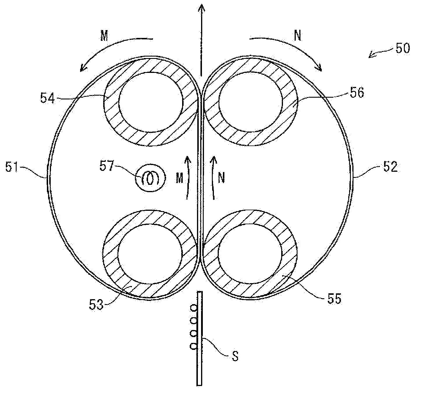
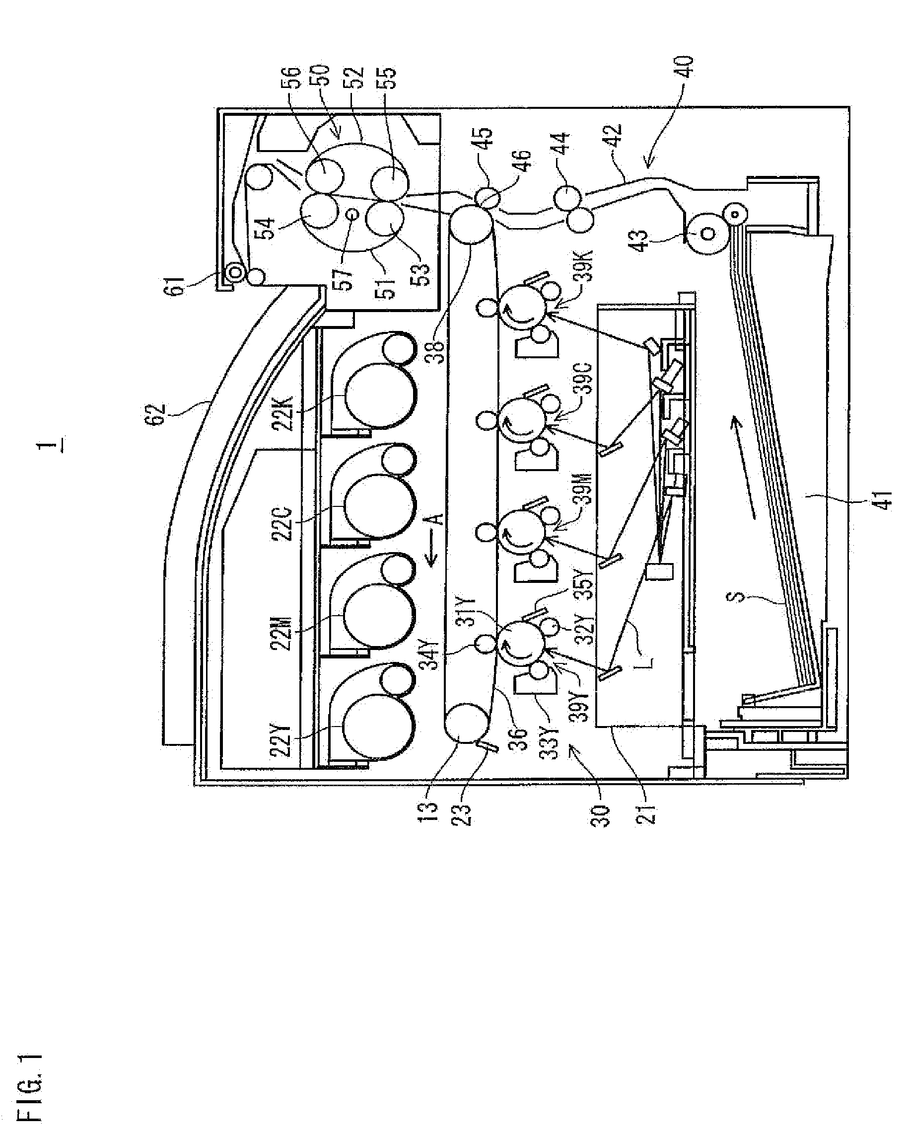
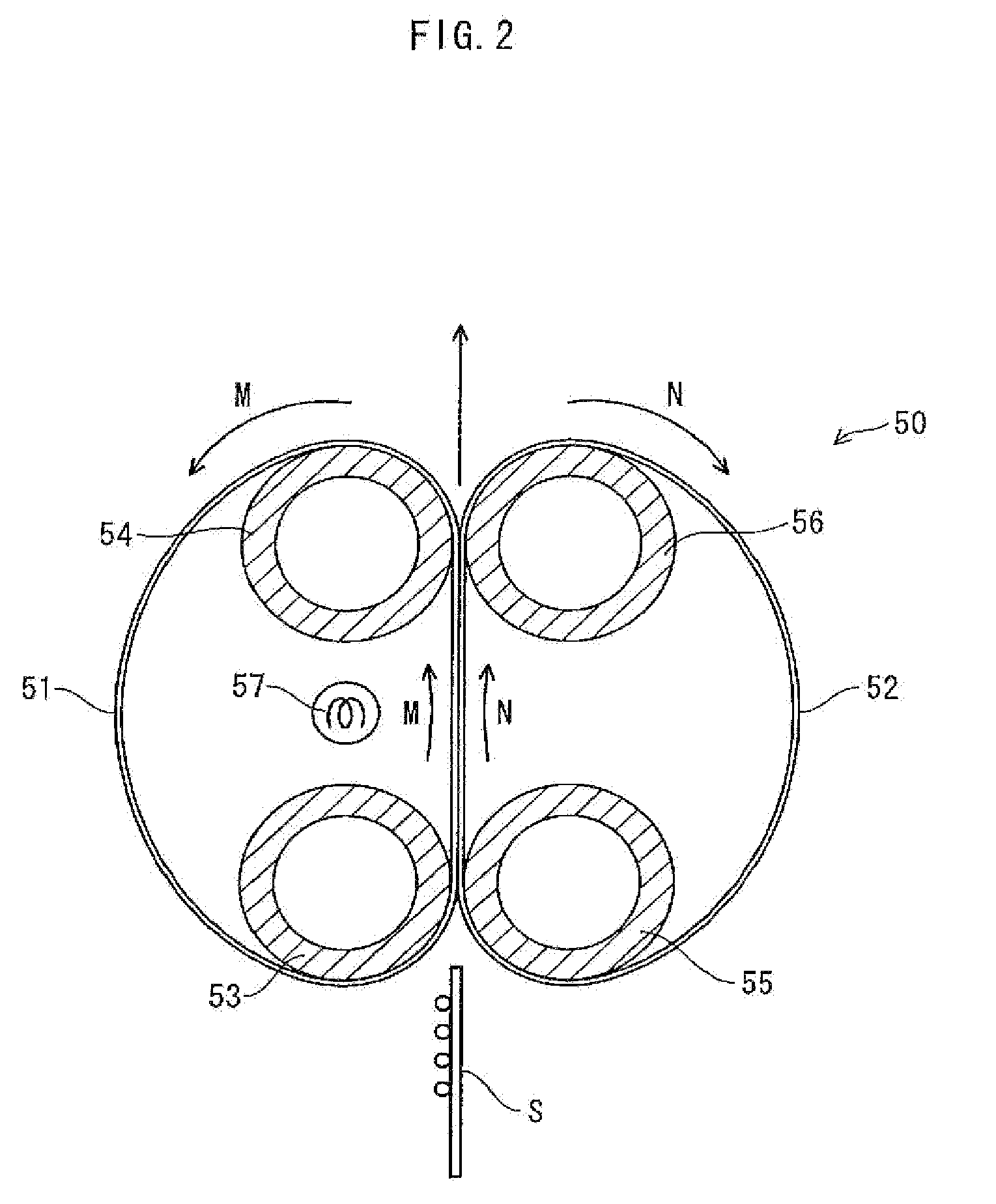
[0043]FIG. 1 is a schematic diagram showing a structure of a tandem-type color digital printer (hereinafter, referred to as simply “printer”) which uses a fixing device pertaining to the present invention as a fixing part. As shown in FIG. 1, a printer 1 includes an image processing part 30, a sheet conveying part 40, and a fixing device 50. The image processing part 30 forms a toner image; the sheet conveying part 40 conveys a recording sheet S to the image processing unit 30 so that the toner image formed by the image processing part 30 is transferred onto the recording sheet S; and the fixing device 50 constitutes the fixing part fixing the toner image, which has been transferred onto the recording sheet S, to the recording sheet S. Upon receiving an instruction to execute printing (a print job) from a terminal device connected to a network (such as an intra-office LAN), the printer 1 forms a toner image on a recording sheet S in accordance with the instruction.

[0044]The image pr...


PUM


Abstract

First belt 51 suspended on first upstream roller 53 and first downstream roller 54, and second belt 52 suspended on second upstream roller 55 and second downstream roller 56 each have a stiffness such that when assumed to be separated from each other, the first belt 51 and the second belt 52 rotate while maintaining an elliptic shape thereof. One of two portions of the first belt 51 facing each other between the first upstream roller 53 and the first downstream roller 54 and one of two portions of the second belt 52 facing each other between the second upstream roller 55 and the second downstream roller 56 are flat as a result of being brought into pressing contact with each other, and a fixing nip is formed therebetween. A toner image is fixed by being heated by heater lamp 57 when recording sheet S passes through the fixing nip.

Description

[0001]This application is based on application No. 2008-318763 filed in Japan, the content of which is hereby incorporated by references.BACKGROUND OF THE INVENTION[0002](1) Field of the Invention[0003]The present invention relates to a fixing device that thermally fixes an unfixed image formed on a recording sheet to the recording sheet, and an image forming apparatus provided with the fixing device.[0004](2) Related Art[0005]In general, image forming apparatuses such as copiers, printers, facsimiles, and MFPs (Multiple Function Peripherals) have a structure that forms a toner image corresponding to image data, transfers the formed toner image onto a recording sheet, and fixes the transferred toner image to the recording sheet using a fixing device.[0006]FIG. 7 is a cross-sectional schematic view for explaining a structure of a fixing device that forms a fixing nip using a pair of belts. This fixing device 70 has a pair of a first belt 71 and a second belt 72 that apply pressure, f...

Claims


Application Information

Patent Timeline
IPC IPC(8): G03G15/20
CPCG03G2215/2016G03G15/2053
Inventor YAMAMOTO, KOJIMASUDA, FUMIO
Owner KONICA MINOLTA BUSINESS TECH INC
Why Eureka
Try Eureka