Rapid warming-up system and method for multi-compressor lubricating system

A lubricating system and compressor technology, applied in the field of compressor warm-up, can solve problems such as poor fluidity, difficulty in absorbing oil by the oil pump, and high viscosity of lubricating oil, so as to reduce heat load, shorten warm-up time, and reduce The effect of footprint

Pending Publication Date: 2021-11-02
SINOPEC OILFIELD EQUIP CORP
View PDF4 Cites 0 Cited by
  • Summary
  • Abstract
  • Description
  • Claims
  • Application Information

AI Technical Summary

Problems solved by technology

However, the viscosity of lubricating oil is greatly affected by its temperature. In some areas, due to the low temperature in winter, the viscosity of lubricating oil is high and the fluidity is poor, making it difficult for the oil pump to absorb oil. Therefore, it is necessary to check the crankcase before starting the compressor. The lubricating oil in the (oil pool) is heated to make the oil temperature reach the minimum start-up temperature

Method used


Image

  • Rapid warming-up system and method for multi-compressor lubricating system
  • Rapid warming-up system and method for multi-compressor lubricating system
  • Rapid warming-up system and method for multi-compressor lubricating system

Examples


Embodiment 1

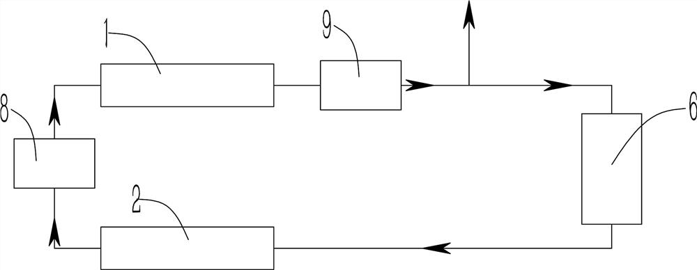
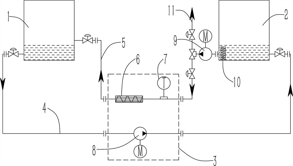
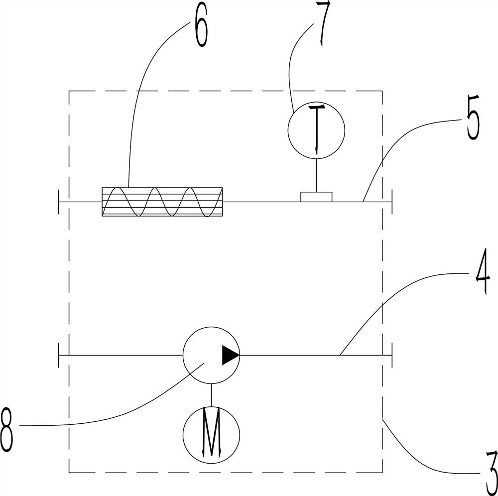
[0030] Such as Figure 1~3 As shown, the rapid warm-up system and method for multiple compressor lubrication systems includes a replacement heating module 3 installed between the operating compressor 1 and the warm-up compressor 2. The replacement heating module 3 includes a return line 4 and a replacement Pipeline 5, the operating compressor 1 communicates with the warm-up compressor 2 through the return pipeline 4 and the replacement pipeline 5 to form a circuit, the replacement pipeline 5 is provided with a baffle heater 6, and the return pipeline 4 is provided with The first oil pump 8;

[0031] The low-temperature lubricating oil in the warm-up compressor 2 is heated by the baffle heater 6 on the replacement pipeline 5, and then passed into the running compressor 1, and mixed with the high-temperature lubricating oil in the running compressor 1, and then The first oil pump 8 on the return line 4 is driven into the warm-up compressor 2, and the low-temperature lubricating...

Embodiment 2

[0042] Such as Figure 1~3 , combined with Example 1 to further illustrate: connect the replacement heating module 3 with the operating compressor 1 and the warm-up compressor 2 to form a circuit; open the control valve to connect the replacement pipeline 5, and start the heater in the warm-up compressor 2 10. Ensure the fluidity of the cooling oil in the warm-up compressor 2; start the second oil pump 9 to quickly heat the lubricating oil in the warm-up compressor 2 through the baffle heater 6 and then pass it into the running compressor 1 ;The lubricating oil passed into the operating compressor 1 is fully mixed with the hot oil in the operating compressor 1, and the waste heat in the operating compressor 1 is used to speed up the heating speed of the cold oil; open the control valve to connect the return line 4. Start the first oil pump 8, and control the flow rate of the first oil pump 8 and the second oil pump 9 to be the same, so that the hot oil in the operating compres...


PUM


Abstract

The invention provides a rapid warming-up system and method for a multi-compressor lubricating system. Cold lubricating oil and hot lubricating oil of two or more compressors are rapidly heated, mixed and replaced through an external replacement heating module, the waste heat of oil in the lubricating system is fully recovered to increase the oil temperature of other lubricating systems, and energy is effectively saved. The warm-up time of the compressor lubricating system is greatly shortened, the replacement heating module is designed to be capable of being rapidly mounted and dismounted, and the occupied area of the lubricating system can be reduced. The warming-up time of the compressors is greatly shortened, and the time cost is saved. The waste heat of the lubricating oil is fully utilized, the heat load of an oil cooler can be effectively reduced, and the energy is saved.

Description

technical field [0001] The invention relates to the technical field of compressor warm-up, in particular to a rapid warm-up system and method for lubrication systems of multiple compressors. Background technique [0002] The compressor lubrication system is the key link to ensure the normal operation of the compressor. It can effectively reduce the wear of the friction pair and reduce the working temperature of the parts. However, the viscosity of lubricating oil is greatly affected by its temperature. In some areas, due to the low temperature in winter, the viscosity of lubricating oil is high and the fluidity is poor, making it difficult for the oil pump to absorb oil. Therefore, it is necessary to check the crankcase before starting the compressor. The lubricating oil in the (oil pool) is heated to make the oil temperature reach the minimum start-up temperature. Due to the low temperature of the lubricating oil and the large oil pool, the heating time of the lubricating ...

Claims


Application Information

Patent Timeline
IPC IPC(8): F04B39/02F04B39/06
CPCF04B39/02F04B39/06
Inventor 刘文军侯小兵黄远明王有朋闻海波
Owner SINOPEC OILFIELD EQUIP CORP
Why Eureka
Try Eureka