Belt Fuser for an Electrophotographic Printer

a technology of electrophotography printer and belt fuser, which is applied in the direction of electrographic process equipment, optics, instruments, etc., can solve the problems of not being able to directly apply force to both ends of the belt to form the required fuser nip, and the fusing quality of the belt fuser with the ceramic heater is not as good as that of the hot roll fuser, so as to overcome the disadvantages of low pressure or slow warm-up time, the effect of improving the quality

Active Publication Date: 2010-12-02
LEXMARK INT INC
View PDF18 Cites 7 Cited by
  • Summary
  • Abstract
  • Description
  • Claims
  • Application Information

AI Technical Summary

Benefits of technology

[0009]The present invention meets this need by providing a fuser that combines the advantages of a belt fuser with a ceramic heater and a hot roll fuser, and overcomes the disadvantages of low pressure or slow warm-up time. The fuser provides higher fusing quality than that of a belt fuser with a ceramic heater due to higher force / higher nip pressure and longer fuser lifetime due to a lower friction force.

Problems solved by technology

A hot roll fuser is a high force and pressure fuser that can deliver high print quality, however a hot roll fuser is not an “instant on” fuser having a very short warm-up time due to the huge thermal mass of thick metal core and thick silicone rubber layer coated on the metal core.
While a belt fuser with a ceramic heater or induction heater can be an “instant on” fuser, it is usually only used for low speed color laser printers due to lower belt operating temperatures.
Therefore, a belt fuser with a ceramic heater has difficulty to provide enough heat for high speed fusing.
In addition, the fusing quality of a belt fuser with a ceramic heater is not as good as that of a hot roll fuser.
Since the fusing belt is very thin and flexible, force cannot be directly applied to both ends of the belt to form a required fuser nip.
Since the pressure member is not turning with the belt, friction forces between the contact surfaces of the belt and the pressure member are very high and can wear the belt and ceramic heater, which reduces fuser lifetime.
Even with lubrication between the contact surface of the belt and the stationary pressure member, belt stall still occurs as the lubrication often fails which causes serious wear on heater surface or belt.
The lower force results in lower nip pressure and the lower nip pressure can cause many print quality problems, such as poor fuse grade, mottling, poor uniformity across a page, and transparency defects.

Method used


Image

  • Belt Fuser for an Electrophotographic Printer
  • Belt Fuser for an Electrophotographic Printer
  • Belt Fuser for an Electrophotographic Printer

Examples


Embodiment Construction

[0021]The present invention now will be described more fully hereinafter with reference to the accompanying drawings, in which some, but not all embodiments of the invention are shown. Indeed, the invention may be embodied in many different forms and should not be construed as limited to the embodiments set forth herein; rather, these embodiments are provided so that this disclosure will satisfy applicable legal requirements. Like numerals refer to like elements throughout the views.

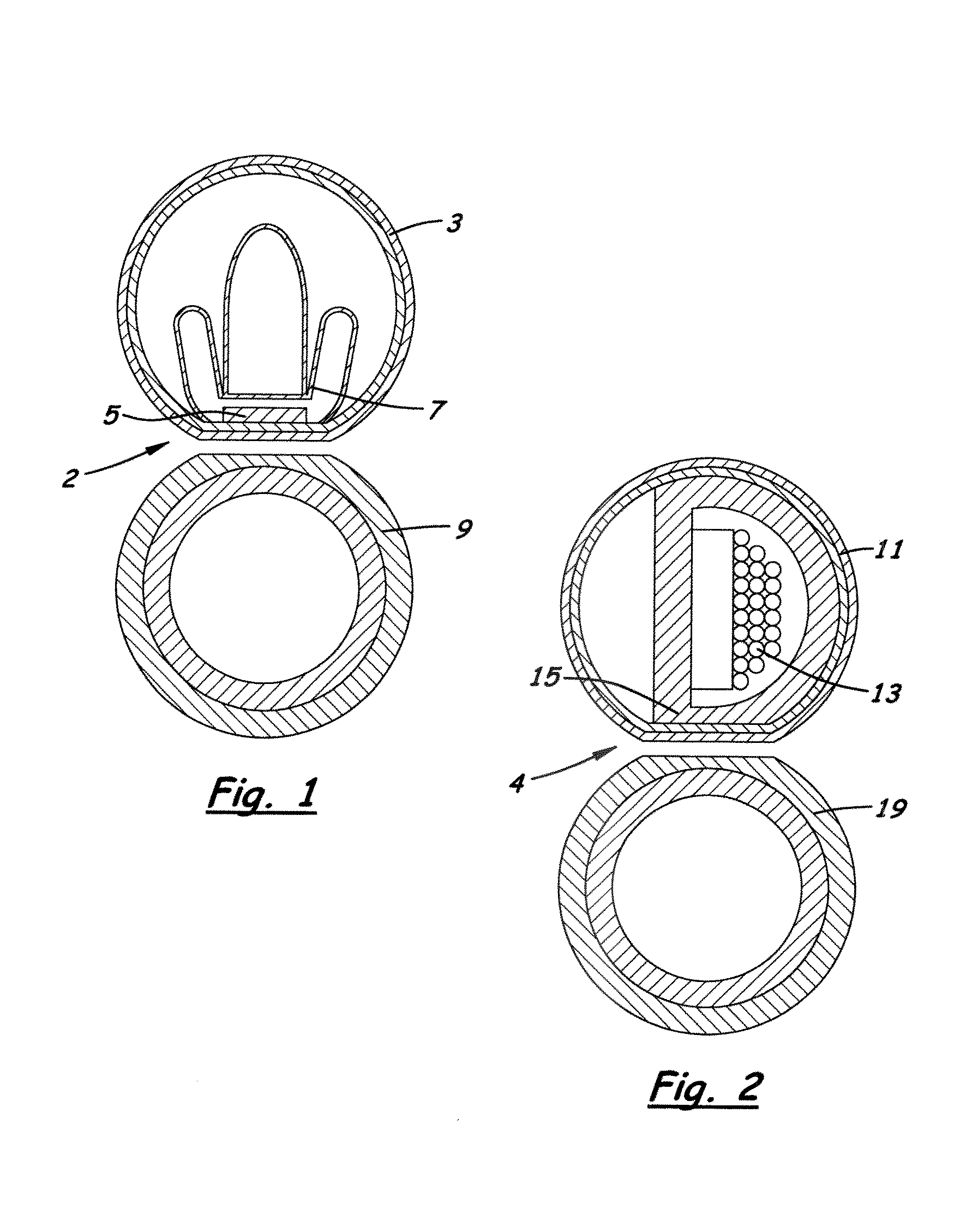
[0022]Referring now to FIG. 1, there is illustrated a side view of a prior art belt fuser with a ceramic heater. In order to form a fuser nip 2, a stationary pressure member 7, a ceramic heater 5 and a heater housing with a steel bracket (not shown) are positioned inside an endless fusing belt 3. The stationary pressure member 7 forces the endless fusing belt 3 to contact a pressure roll 9 to form a fuser nip 2. Stationary pressure member 7 does not turn with the endless fusing belt 3, which results in a...


PUM


Abstract

A fuser and method of use for an electrophotographic imaging device that includes a lamp heater assembly; an endless fusing belt having a flexible tubular configuration and being positioned about the lamp heater assembly and spaced outwardly therefrom; a transparent or translucent pressure tube having an elongated tubular body and a pair of opposite ends, the body being substantially transparent to passage of radiant heat therethrough; a pressure tube support assembly having a frame and a pair of bearings mounted on the frame spaced apart from one another and supporting the pressure tube at the opposite ends of the tubular body thereof such that the tubular body of the pressure tube is positioned around the lamp heater assembly and inside the fusing belt and enables radiant heat generated by the lamp heater to pass through the transparent or translucent pressure tube and heat the fusing belt

Description

CROSS REFERENCES TO RELATED APPLICATIONS[0001]None.BACKGROUND[0002]1. Field of the Invention[0003]The present invention relates generally to electrophotographic imaging device and, more particularly, to fusers of electrophotographic imaging devices.[0004]2. Description of the Related Art[0005]In the electrophotographic (EP) imaging process used in printers, copiers and the like, a photosensitive member, such as a photoconductive drum or belt, is uniformly charged over an outer surface. An electrostatic latent image is formed by selectively exposing the uniformly charged surface of the photosensitive member. Toner particles are applied to the electrostatic latent image, and thereafter the toner image is transferred to the media intended to receive the final permanent image. The toner is fixed to the media by the application of heat and pressure in a fuser. A fuser may include a heated roll and a backup roll forming a fusing nip through which media passes, known as a hot roll fuser. A...

Claims


Application Information

Patent Timeline
Patent Type & Authority Applications(United States)
IPC IPC(8): G03G15/20
CPCG03G15/2053G03G2215/2025G03G2215/2035
Inventor CAO, JICHANGWU, SCOTT SHIAOSHIN
Owner LEXMARK INT INC
Why Eureka
Try Eureka