Oscillating Diaphragm Fan Having Coupled Subunits and a Housing Having an Oscillating Diaphragm Fan of this Type

a diaphragm fan and diaphragm technology, which is applied in the direction of positive displacement liquid engines, instruments, computing, etc., can solve the problem that dirt cannot be sucked in from the surroundings, and achieve the effect of avoiding the operation of fan restrictions due to gradual contamination and advantageous structural properties

Active Publication Date: 2010-06-17
SIEMENS AG
View PDF48 Cites 14 Cited by
  • Summary
  • Abstract
  • Description
  • Claims
  • Application Information

AI Technical Summary

Benefits of technology

[0007]It is therefore an object of the invention to provide an oscillating diaphragm fan in which the operational restrictions of the function of the fan due to gradual contamination can be avoided and to allow an especially advantageous structural integration of an oscillating diaphragm fan of this type into a housing.
[0009]The oscillating diaphragm fan in accordance with the invention advantageously provides air-coupled actuator chambers of the subunits that are completely encapsulated outwardly. Consequently, no air exchange with the surroundings is necessary for pressure compensation, regardless of the oscillations of the magnetic systems located therein. As a result, dirt cannot be sucked in from the surroundings and thereby deposited in the magnetic systems located in the actuator chambers. Due to the excitation, which is phase-shifted in accordance with the invention, of the magnetic systems and of the oscillating diaphragms connected thereto, a compensation of under-pressures or over-pressures in the system of the air-coupled actuator chambers is continually ensured via the pressure compensation means.
[0010]In an embodiment, the oscillating diaphragm fan is configured as a double system of two coupled subunits. As a result, the magnetic systems of the subunits are advantageously activated in opposition, i.e., with a phase shift of substantially 180°. The oscillating diaphragms of the subunits therefore oscillate oppositely to each other. Hence, while the oscillating diaphragm of one subunit is pressed outward by the associated magnetic system and consequently causes an under-pressure in the respective actuator chamber, the oscillating diaphragm of the other subunit is simultaneously pulled inwardly by the associated magnetic system and, consequently, an overpressure is created in the respective actuator chamber. In accordance with this embodiment, the means for compensating pressure between the actuator chambers ensures compensation of under-pressures and over-pressures in the overall system.

Problems solved by technology

As a result, dirt cannot be sucked in from the surroundings and thereby deposited in the magnetic systems located in the actuator chambers.

Method used


Image

  • Oscillating Diaphragm Fan Having Coupled Subunits and a Housing Having an Oscillating Diaphragm Fan of this Type
  • Oscillating Diaphragm Fan Having Coupled Subunits and a Housing Having an Oscillating Diaphragm Fan of this Type

Examples


Embodiment Construction

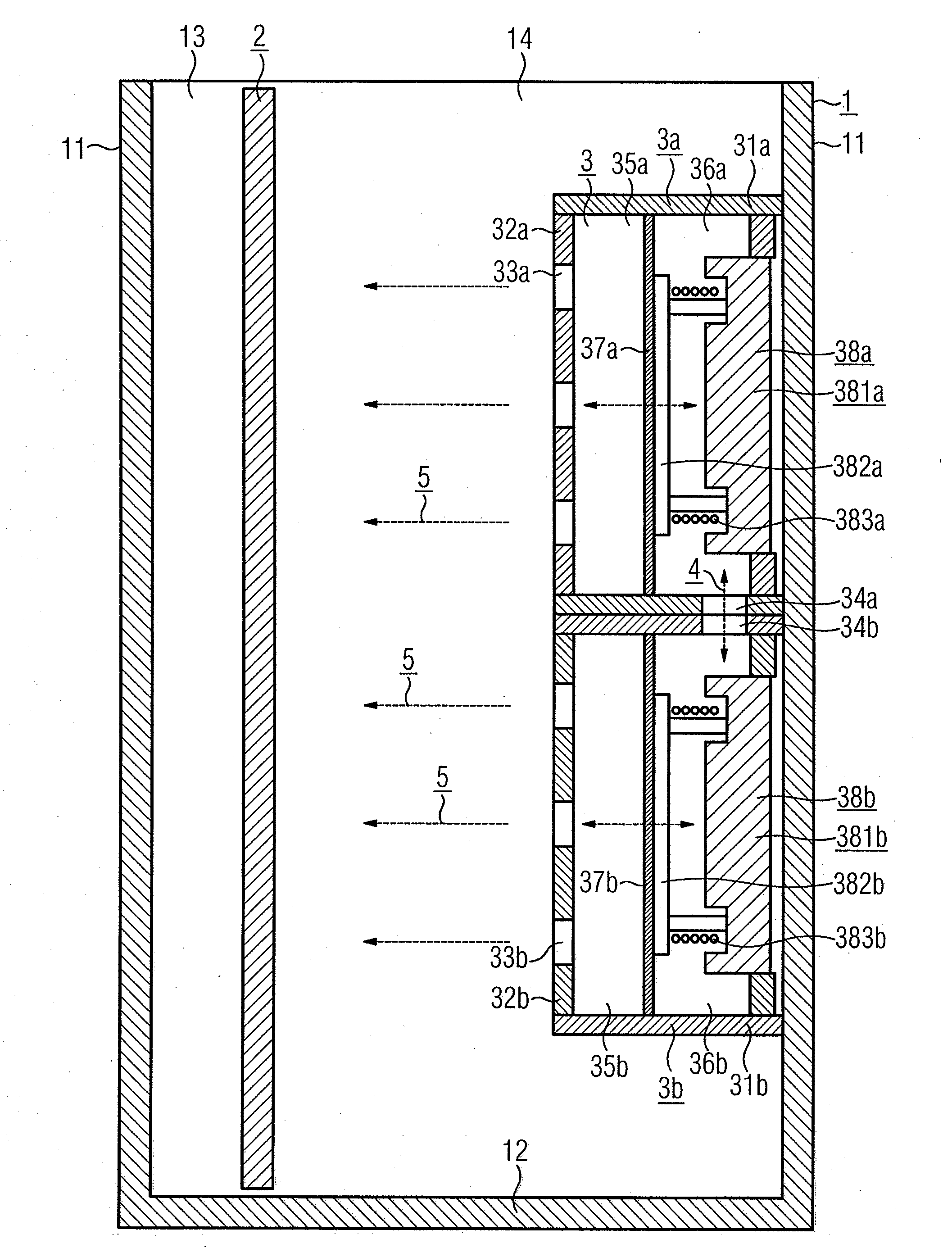
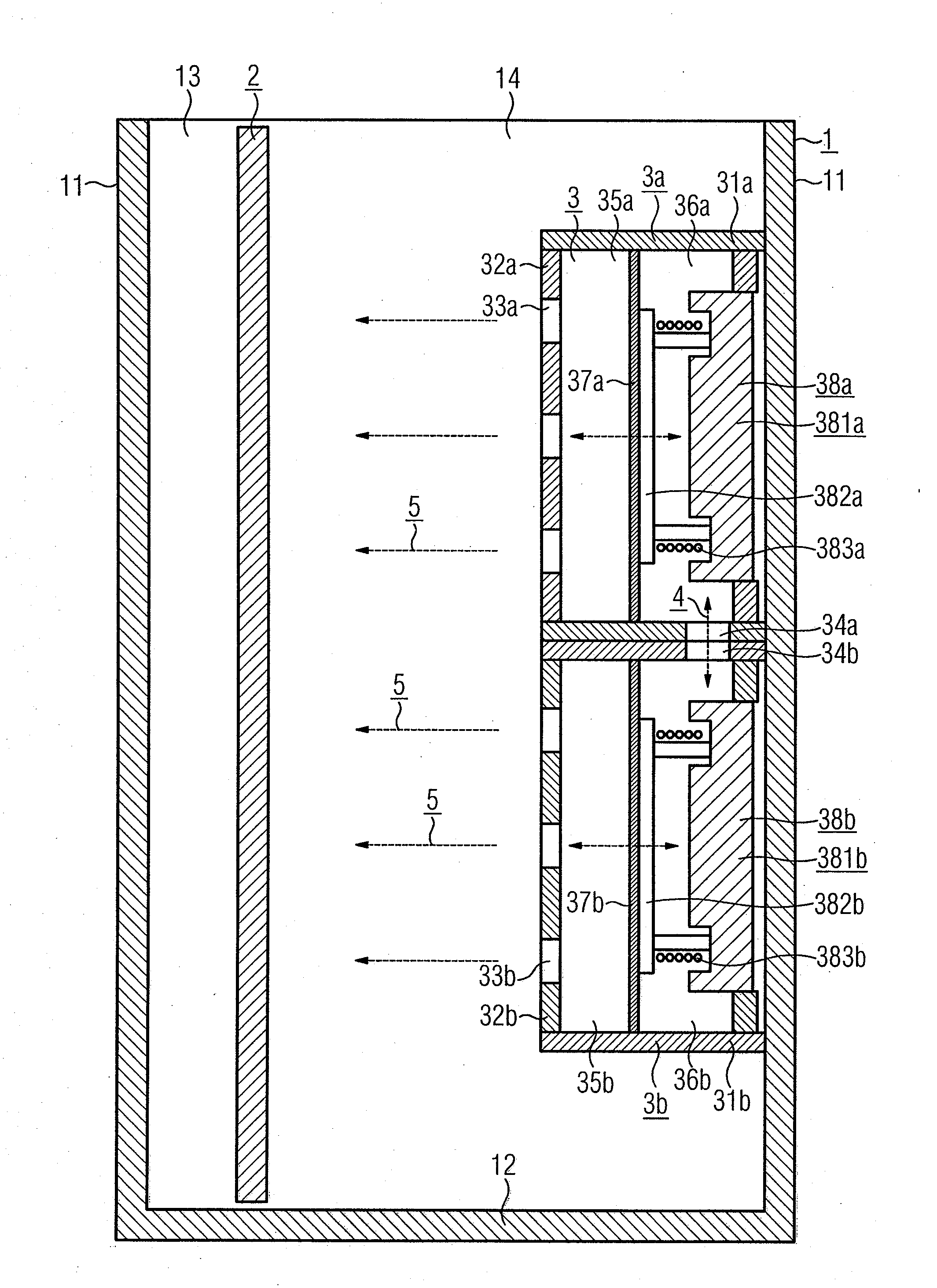
[0017]The FIGURE shows an exemplary sectional view of a housing 1, such as an electronic housing, which includes, for example, a bottom 12 and two vertical side walls 11 that are disposed opposite to one another. A ventilation orifice 14 extending in the drawing plane is located, for example, on the top-side 13 of the housing 1. As a result, it is possible for air to naturally exchange with the surroundings and vent due to convection. However, dirt particles may also pass via this ventilation orifice 14 into the inside of the housing 1 and be deposited therein.

[0018]In an embodiment, the housing 1 may contain a multiplicity of electrical elements which generate thermal heat loss, and from which heat therefore has to be removed. A vertically installed electronic circuit board 2 is illustrated symbolically in the FIGURE as an exemplary installation part of this type. An oscillating diaphragm fan 3 constructed in accordance with the exemplary embodiment is placed on the inside of the o...


PUM


Abstract

An oscillating diaphragm fan having a plurality of subunits which each have an oscillating diaphragm that is excited by a magnetic system in an actuator chamber, wherein the air pulsation generated by oscillating diaphragm is discharged outwardly, the actuator chambers of the subunits are connected via means for compensating pressure and are encapsulated outwardly, and the magnetic systems of the subunits are excited out of phase with each other.

Description

BACKGROUND OF THE INVENTION[0001]1. Field of the Invention[0002]The present invention relates to oscillating diaphragm fans and, more particularly, to an oscillating diaphragm fan having coupled subunits and a housing having the oscillating diaphragm fan.[0003]2. Description of the Related Art[0004]Fans with moving parts are known. In such fans, it is known to mount the movable parts such that they are free of friction and do not contact each another. The set-up of these fans is in some way comparable to the operation of a loudspeaker. Fans of this type are known as “jet cooler” or “jet generator” fans, and are designated below as oscillating diaphragm fans.[0005]Oscillating diaphragm fans include an oscillating diaphragm which is held in a housing and which is excited by a magnetic system located in an actuator chamber. The air pulsation generated by the oscillating diaphragm is discharged outwardly. If, for example, the oscillating diaphragm fan is placed inside an electronic hous...

Claims


Application Information

Patent Timeline
Patent Type & Authority Applications(United States)
IPC IPC(8): F04B17/03
CPCF04B43/04F04B43/043G06F1/203G06F1/20F04F7/00
Inventor BUSCH, KLAUSSCHARF, CHRISTIANWIESNER, CHRISTOPH
Owner SIEMENS AG
Why Eureka
Try Eureka