Sensor holder, holder unit in which blood sensor is mounted to the sensor holder, and blood testing device to which the holder unit is mounted

Inactive Publication Date: 2010-06-17
PANASONIC HEALTHCARE HLDG CO LTD
View PDF7 Cites 10 Cited by
  • Summary
  • Abstract
  • Description
  • Claims
  • Application Information

AI Technical Summary

Benefits of technology

[0011]The present invention solves this problem, and it is an object thereof to provide a sensor holder with which the deposition of blood can ...

Problems solved by technology

Depositing blood at the finger holding part 12 is...

Method used


Image

  • Sensor holder, holder unit in which blood sensor is mounted to the sensor holder, and blood testing device to which the holder unit is mounted
  • Sensor holder, holder unit in which blood sensor is mounted to the sensor holder, and blood testing device to which the holder unit is mounted
  • Sensor holder, holder unit in which blood sensor is mounted to the sensor holder, and blood testing device to which the holder unit is mounted

Examples


embodiment 1

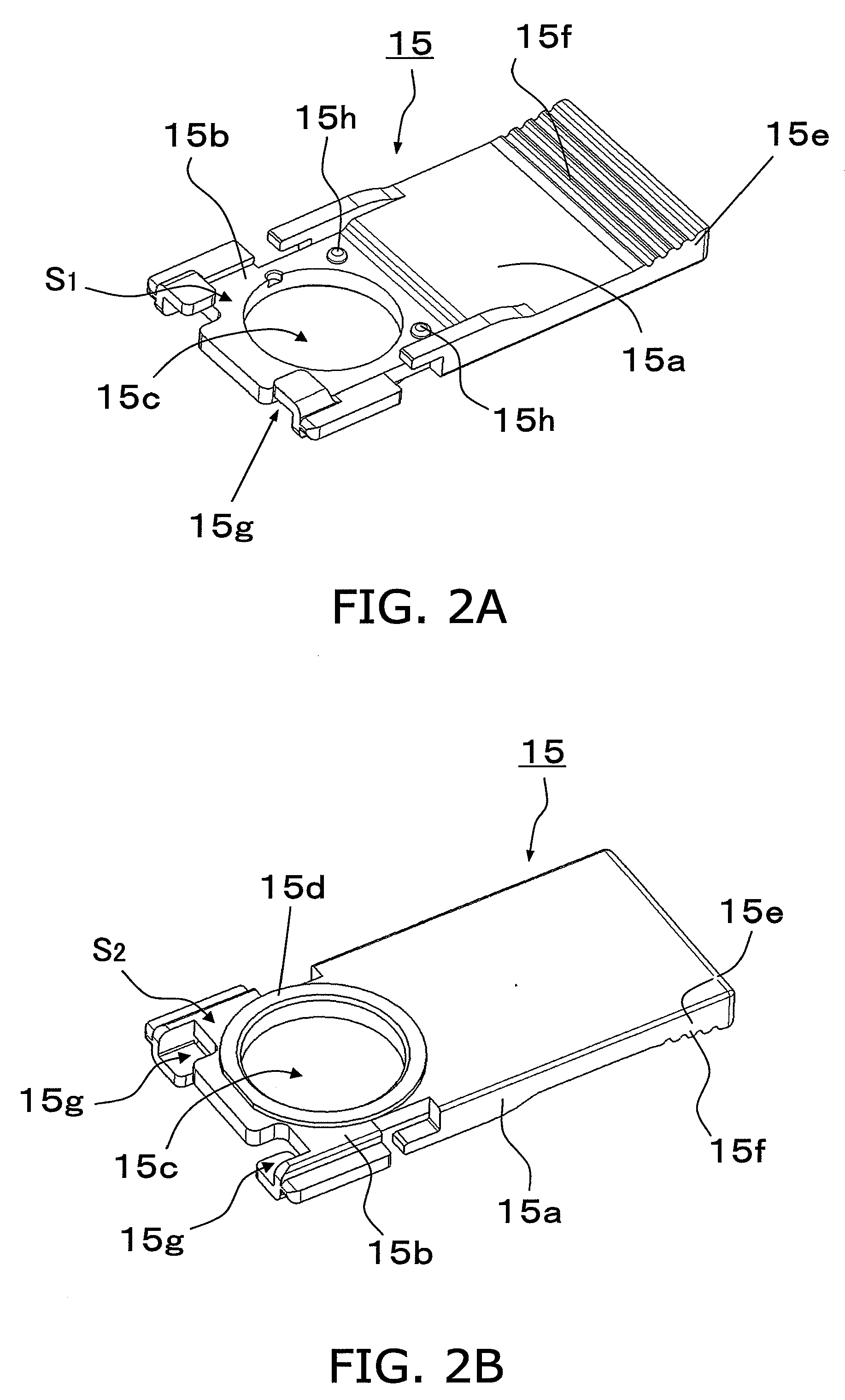
[0042]FIG. 2A is an oblique view of a sensor holder 15 pertaining to Embodiment 1, as seen from one side (a first face side), and FIG. 2B is an oblique view of the sensor holder 15 as seen from the other side (a second face side). FIG. 2C is an oblique view of a holder unit 16 pertaining to Embodiment 1, as seen from one side (the first face side), and FIG. 2D is an oblique view of the holder unit 16 as seen from the other side (the second face side). The holder unit 16 is such that a blood sensor 30 is mounted to the sensor holder 15.

[0043]As shown in FIGS. 2A to 2D, the sensor holder 15 is formed from a main body center part 15a, a sensor mounting part 15b that is provided at one end of the main body center part 15a and on which the blood sensor 30 is placed, a finger holding part 15d provided on the opposite side of the blood sensor 30 across the sensor mounting part 15b, and a grip 15e provided at the other end of the main body center part 15a.

[0044]As shown in FIGS. 2A and 2B,...

embodiment 2

[0079]Embodiment 2 differs from Embodiment 1 in that an opening 52a (corresponds to the opening 22a in Embodiment 1) into which the holder unit 16 is inserted is provided in the middle of the lower edge of a case 52 (corresponds to the case 22 in Embodiment 1). Therefore, the finger on either the one hand 17 or the other hand 18 can be punctured. In the following description of the drawings, those components that are the same as in Embodiment 1 are numbered the same. Also, since the mounting of the parts in the case 52 not discussed below is the same as the mounting of the parts in the case 22 pertaining to Embodiment 1, it will not be described again. The same applies to the other embodiments given below.

[0080]FIGS. 11A and 11B are oblique views of a blood testing device 51 pertaining to Embodiment 2 (corresponds to the blood testing device 21 in Embodiment 1), as seen from the front face side. More specifically, FIG. 11A shows the state before the holder unit 16 is inserted into t...

embodiment 3

[0083]Embodiment 3 differs from Embodiment 1 in that a cut-out 63 is provided at the lower right corner of a case 62 (corresponds to the case 22 in Embodiment 1), and that an opening 62a (corresponds to the opening 22a in Embodiment 1) into which the holder unit 16 is inserted is provided to the cut-out 63. Therefore, the cut-out 63 forms a larger space above and below the grip 15e of the holder unit 16, and this makes it easier to remove and install the holder unit 16.

[0084]FIGS. 12A and 12B are oblique views of a blood testing device 61 pertaining to Embodiment 3 (corresponds to the blood testing device 21 pertaining to Embodiment 1), as seen from the front face side. More specifically, FIG. 12A shows the state before the holder unit 16 is inserted into the opening 62a. As shown in FIG. 12A, the cut-out 63 is formed at the lower right corner of the case 62 of the blood testing device 61. Also, the opening 62a is provided on the inside of the cut-out 63, that is, on the side of the...


PUM


Abstract

A sensor holder comprises a sensor mounting part having a first face on which a blood sensor is placed, a second face provided on the opposite side from the first face, and a through-hole that goes from the first face to the second face and is large enough to allow a laser beam to pass through; a finger holding part that is provided on the second face and surrounds the through-hole, and a grip that sticks out from the blood testing device when the sensor holder is mounted to the blood testing device.

Description

CROSS REFERENCE TO RELATED APPLICATIONS[0001]This application is based upon and claims the benefit of priority from prior Japanese Patent Application No. 2008-320444, filed on Dec. 17, 2008; the entire contents of which are incorporated herein by reference.BACKGROUND ART[0002]1. Field of the Invention[0003]The present invention relates to a sensor holder, to a holder unit in which a blood sensor is mounted to the sensor holder, and to a blood testing device to which the holder unit is mounted.[0004]2. Description of the Related Art[0005]A conventional blood testing device (see national publication JP 2001-515377, for example) will now be described. As shown in FIG. 1, the conventional blood testing device 1 comprises a main body 2 having an elliptical cylindrical shape, and a lid 3 that is fitted to the main body 2. The main body 2 comprises a guide 4 that is provided on an end face of the main body 2 and guides the fitting of the lid 3, a connector 5 provided to the guide 4, a bloo...

Claims


Application Information

Patent Timeline
IPC IPC(8): G01N33/48B01L9/00
CPCA61B5/1411B01L2400/0406A61B5/14535A61B5/151A61B5/15134B01L3/5027B01L9/527B01L2200/04B01L2200/085B01L2300/027B01L2300/048B01L2300/0645B01L2300/0672B01L2300/0825B01L2300/0887A61B5/14532A61B5/150022A61B5/150259A61B5/150358A61B5/15113A61B5/15136A61B5/157
Inventor NISHIDA, TAKESHITAKASHIMA, TETSUYAHASHIMOTO, YOHEI
Owner PANASONIC HEALTHCARE HLDG CO LTD
Why Eureka
Try Eureka