Controller of drive device for vehicle

a control device and vehicle technology, applied in the direction of motor/generator/converter stopper, propulsion using engine-driven generators, external condition input parameters, etc., can solve the problems of increasing the size of the drive apparatus, the power transmission mechanism having such combined advantages has not been put into practical use, and the first electric motor to be large-sized with an increase in engine output, etc., to achieve rapid drive torque and smooth change of drive torqu

Active Publication Date: 2010-06-17
TOYOTA JIDOSHA KK
View PDF21 Cites 51 Cited by
  • Summary
  • Abstract
  • Description
  • Claims
  • Application Information

AI Technical Summary

Benefits of technology

[0072]The stepwise change of the total gear ratio depending on the shifting action of the shifting portion is executed more rapidly, than the continuous change thereof. Consequently, the drive apparatus functioning as the continuously variable transmission can smoothly changes the drive torque thereof, and can change the gear ratio thereof to rapidly obtain the drive torque.

Problems solved by technology

However, no power transmitting mechanism having such combined advantages has been put into practical use yet.
This inevitably causes the first electric motor to be made large-size with an increase in an output of the engine.
Thus, an issue arises with the occurrence of an increase in size of the drive apparatus.
Alternatively, since a part of the engine output is transmitted to the drive wheel after converted into electric energy once, the fuel consumption may be worsened depending on the running condition of the vehicle such as the high speed running.
Similar problem occurs when the above power distributing device is used as the transmission of which shifting ratio is changed electrically, for example the electrically controlled CVT.
Therefore, under a situation where the vehicle runs under high load of the engine like when the vehicle runs on the ascending road, reaction torque (load torque) born with the first electric motor increases, resulting in likelihood of a shortage occurring in the drive force depending on the performance of the first electric motor.
However, suppressing the upshift has resulted in likelihood of an increase in load torque of the second electric motor.
Further, under a situation where the regeneration amount is unavailable to increase due to a full charge or the like of the battery, there has been a probability with a difficulty of obtaining the required drive force source brake.
However, if the regeneration amount is unavailable to increase due to the full charge of the battery, there has been a probability with a difficulty occurring in obtaining a given drive condition and a target speed reduction magnitude set by a driver.
However, changing the cylinder number of the engine and the regeneration amount allows the speed reduction magnitude to be controlled, resulting in likelihood of a difficulty arising in obtaining the given drive condition and the target speed reduction magnitude set by the driver.
Further, even with the vehicular drive apparatus, disclosed in Patent Publication 3, which is structured to address the issue of the drive apparatus for hybrid vehicle, likewise, there has been likelihood of a difficulty arising in obtaining the given drive condition and the target speed reduction magnitude set by the driver during the speed reduction running.
So, if a uniform regeneration amount is set for the speed reduction running to allow the electric motor to perform the regeneration in accord with an engine state in increased engine drag torque, that is, in other words, a lessened level of the regeneration amount achieved by the electric motor, there has been likelihood of the occurrence of a deterioration in fuel consumption.
This is because the regeneration amount is unavailable to increase even under the engine state available to obtain the increased regeneration amount.
Even with the vehicular drive apparatus structured to address the issue of the drive apparatus for hybrid vehicle disclosed in Patent Publication 3, there has been likelihood that if the electric motor uniformly performs the regeneration during the speed reduction running, the regeneration amount is unavailable to increase with a resultant deterioration in fuel consumption.

Method used


Image

  • Controller of drive device for vehicle
  • Controller of drive device for vehicle
  • Controller of drive device for vehicle

Examples


embodiment 1

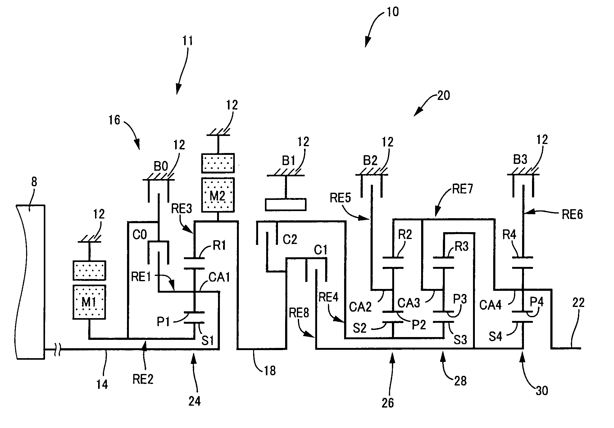
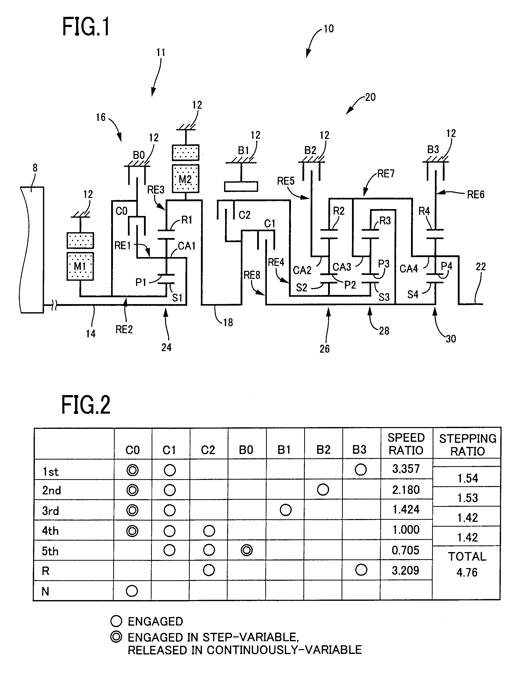
[0121]FIG. 1 is a skeleton view explaining a shifting mechanism 10 constructing a part of a drive apparatus of a hybrid vehicle according to one embodiment of the present invention. The shifting mechanism 10 includes an input shaft 14, a differential portion 11, an automatic transmission portion i.e., automatic shifting portion 20, and an output shaft 22 all coaxially disposed in a transmission case 12 (hereinafter briefly referred to as “case 12”) as a non-rotatable member fixed to a vehicle body. The input shaft 14 as an input rotation member is fixed to the case 12. The differential portion 11 is connected to the input shaft 14 directly or indirectly via a pulsation absorbing damper (vibration damping device) not shown. The automatic transmission portion 20 functioning as a step-variable type transmission that is the shifting portion is disposed between the differential mechanism 11 and the output shaft 22 to be connected thereto in series. The output shaft 22 as an output rotati...

embodiment 2

[0275]FIG. 15 is a skeleton view explaining structure of a shifting mechanism 70 according to other embodiment of the present invention. FIG. 16 is an operation Table indicating a relation between a shifting position of the shifting mechanism 70, and operation combinations of hydraulic-type frictionally engaging devices used therefor. FIG. 17 is a collinear chart explaining a shifting operation of the shifting mechanism 70.

[0276]Like the illustrated embodiment described above, the shifting mechanism 70 comprises the differential portion 11 including the first electric motor M1, the power distributing mechanism 16 and the second electric motor M2, and an automatic transmission portion or the automatic shifting portion 72 with three forward-gear positions connected to the differential portion 11 and the output shaft 22 in series via the transmitting member 18. The power distributing mechanism 16 includes the first planetary gear unit 24 of the single pinion type having a given gear ra...

embodiment 3

[0291]FIG. 18 is a functional block diagram illustrating an essence of another example of a control function to be executed by the electronic control device 40. In the illustrated embodiment shown in FIG. 18, the target speed reduction magnitude G* is set for the speed reduction running of the vehicle and brake torque is generated so as to achieve the target speed reduction magnitude G*. Although this brake torque is obtained on, for instance, the regeneration, engine brake and wheel brake or the like, the brake on the regeneration is effectuated with top priority in light of the energy efficiency. As will be apparent from the shifting lines of FIG. 6, the differential portion 11 is switched to the continuously variable shifting state during the speed reduction running with the accelerator pedal being released. In achieving the target speed reduction magnitude G* with the regeneration, the hybrid control means 52 initiates the fuel cutoff operation for stopping the operation of the ...


PUM


Abstract

A control device is provided for a vehicular drive apparatus, having a differential mechanism and a transmission, for miniaturizing the differential mechanism and/or providing improved fuel economy while preventing a busy shift. With the provision of a switching clutch C0 or a switching brake B0, a transmitting mechanism 10 can be placed in a continuously variable shifting state and a step-variable shifting state whereby the vehicular drive apparatus has combined advantages including a fuel saving effect of the transmission, enabled to electrically change a gear ratio, and a high transmitting efficiency of a gear type transmitting device enabled to mechanically transmit drive power. With a total speed ratio γT set to a lower vehicle speed gear ratio than that for a given running state, if a required drive force or a drive force source brake is unavailable or if load torque of an electric motor is deviated from an allowable range, switching control mean 50 switches a differential portion 11 to the step-variable shifting state for thereby obtaining larger drive force or drive force source brake than those for the given running state without causing load torque of the electric motor from deviating from the allowable range while preventing the busy shift.

Description

TECHNICAL FIELD[0001]The present invention relates to vehicular drive apparatuses each having a differential mechanism operative to perform a differential action and an electric motor and, more particularly, to a technology of miniaturizing the electric motor or the like.BACKGROUND ART[0002]There has heretofore been known a drive apparatus of a vehicle including a differential device through which an output of a drive power source, such as an engine or the like, is distributed to a first electric motor and an output member, and a second electric motor disposed between the output member and drive wheels. Such drive apparatus for a hybrid vehicle is disclosed for example in a Patent Documents 1, 3 and 5. It includes a differential mechanism being comprised of a planetary gear unit and performing a differential action for mechanically transmitting a major part of power outputted from the engine to drive wheels. A remaining part of power from the engine is electrically transmitted from ...

Claims


Application Information

Patent Timeline
Patent Type & Authority Applications(United States)
IPC IPC(8): B60W10/10H02P3/14H02P6/04B60K1/02B60W10/08B60K6/445B60K6/543B60K6/547B60L50/16B60W20/00F16H59/14F16H59/66F16H61/02F16H61/10F16H61/68F16H61/684F16H61/686
CPCB60K6/442Y10T477/23B60L2240/423B60L2240/486B60W10/06B60W10/08B60W10/105B60W10/115B60W30/18072B60W30/19B60W2510/083B60W2510/105B60W2550/142F16H2037/0873F16H2061/6603Y02T10/52Y02T10/6234Y02T10/6239Y02T10/6286Y02T10/642B60K6/445Y02T10/84B60W2552/15Y02T10/40Y02T10/62Y02T10/64
Inventor TABATA, ATSUSHIINOUE, YUJIKAMADA, ATSUSHI
Owner TOYOTA JIDOSHA KK
Why Eureka
Try Eureka