Detection Device And Methods Of Use

a detection device and detection method technology, applied in the direction of fluorescence/phosphorescence, material analysis through optical means, instruments, etc., can solve the problems of difficult to perform concurrent measurements of a number of different fluorescent labels that may be present in a sample (or in different samples), existing fluorometers, and inability to facilitate such multiple-label experiments

Active Publication Date: 2010-06-17
ISOPLEXIS
View PDF14 Cites 31 Cited by
  • Summary
  • Abstract
  • Description
  • Claims
  • Application Information

AI Technical Summary

Benefits of technology

[0021]In one embodiment, the present invention contemplates a method comprising: a) providing an imaging system, said imaging system comprising a non-lasing light source configured such that the emitted light from said source illuminates (and preferably converges on) a flow cell (or portion thereof) comprising an array of biomolecules, said emitted light suitable for causing visible fluorescence of fluorescent compounds; a lens positioned to collect at least a portion of said visible fluorescence; and a light collection means (e.g. a charge coupled device, a CMOS device, or other type of camera) positioned such that said portion of said visible fluorescence collected by said lens passes through toward the light collection means; b) introducing a solution into said flow cell, said solution comprising one or more fluorescent compounds, under conditions such that at least a portion of said fluorescent compounds attaches to at least a portion of said array of biomolecules, so as to create treated biomolecules, and c) imaging said treated biomolecules with said imaging system. In one embodiment of this method, the biomolecules comprises nucleic acid. In one embodiment of this method, the solution comprises oligonucleotides comprising fluorescent tags, wherein a portion of said oligonucleotides hybridize with a portion of said nucleic acid biomolecules of said array.
[0022]In another embodiment, said biomolecules comprise nucleic acid and said solution comprises fluorescently-labeled nucleotides and an enzyme capable of causing at least a portion of said nucleotides to be incorporated into at least a portion of said nucleic acid biomolecules of said array. In one embodiment, said nucleotides are BODIPY-labeled nucleotides. In another embodiment, a second solution is employed comprising one or more enzymes (or chemicals) capable of removing said fluorescent labels. In one embodiment, first and second solutions are used stepwise whereby labels are introduced, imaged, and subsequently removed (the cycle being repeated two times, more preferably 10 times or more).

Problems solved by technology

With conventional devices, moreover, it is also difficult to perform concurrent measurements of a number of different fluorescent labels that may be present in a sample (or in different samples).
Existing fluorometers, however, do not facilitate such multiple-label experiments.

Method used


Image

  • Detection Device And Methods Of Use
  • Detection Device And Methods Of Use
  • Detection Device And Methods Of Use

Examples


Embodiment Construction

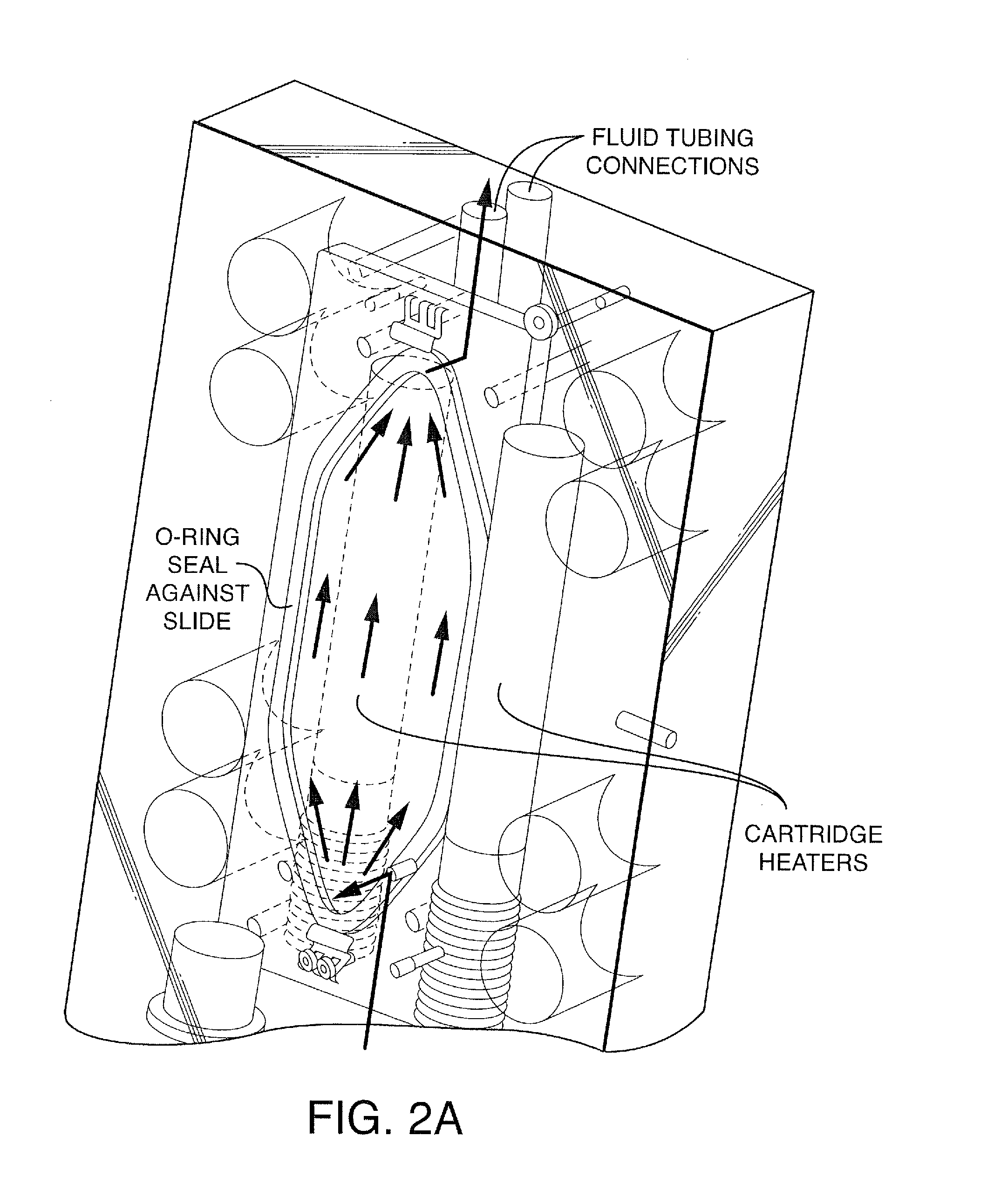
[0030]The present invention contemplates a fluorescent detection system and a flow cell for processing biomolecules (e.g. nucleic acid samples) arrayed on a “chip” or other surface (e.g. microscope slide, etc.). The flow cell permits the user to perform biological reactions, including but not limited to, hybridization and sequencing of nucleic acids.

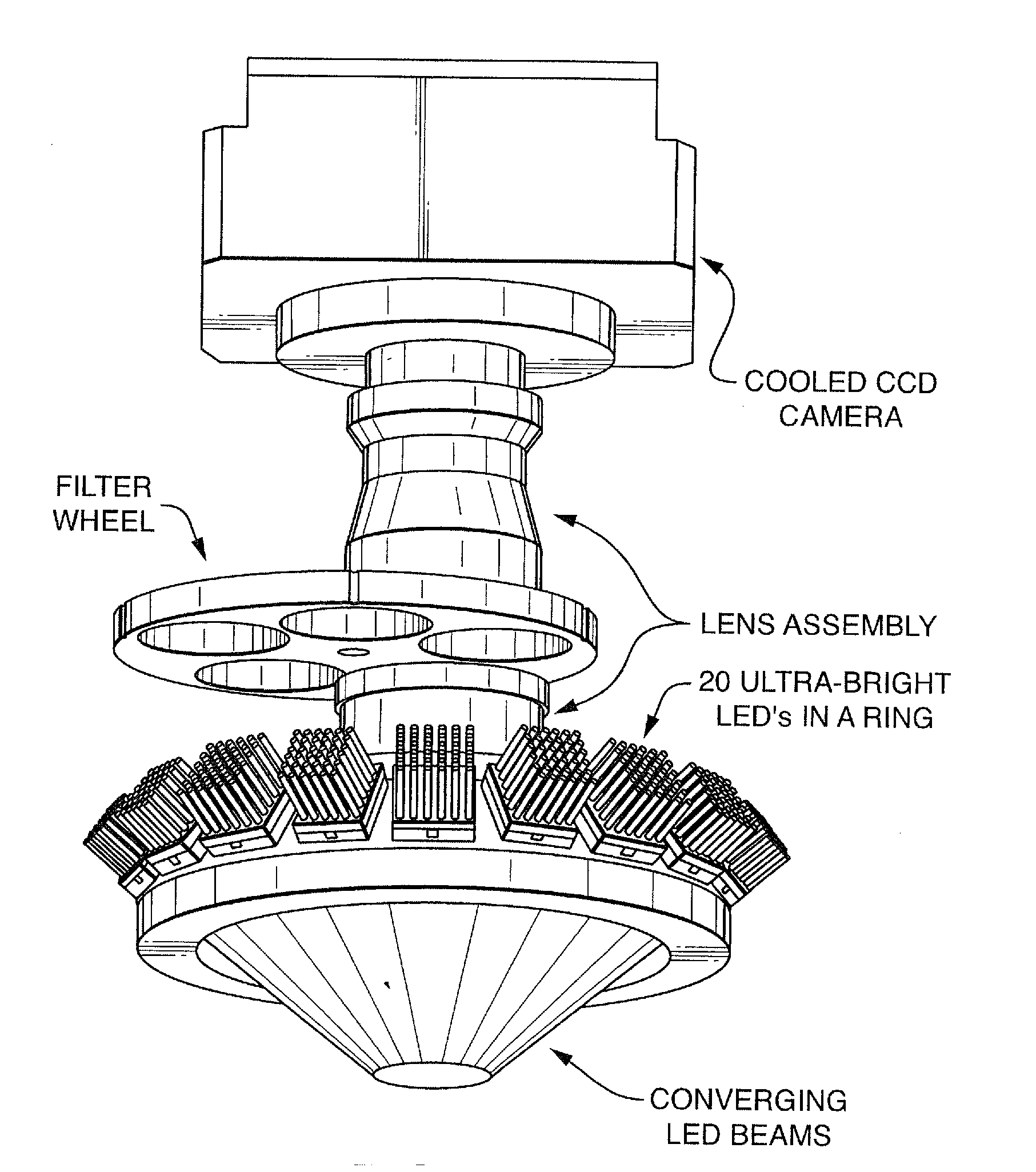
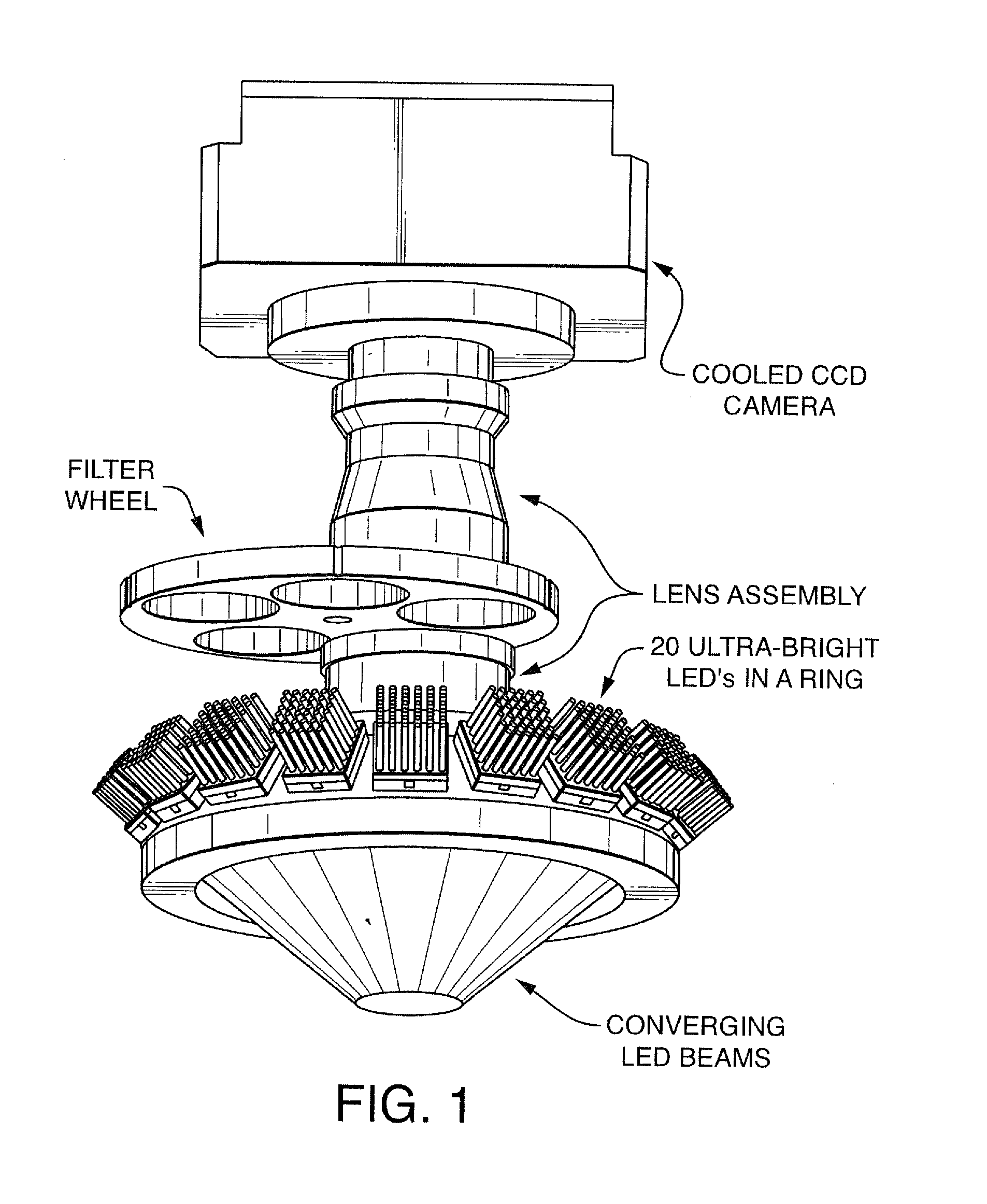
[0031]It is not intended that the present invention be limited to particular light sources. By way of example only, the system can employ ultra-bright LEDs (such as those available from Philips Lumileds Lighting Co., San Jose, Calif.) of different colors to excite dyes attached to the arrayed nucleic acids. These LEDs are more cost effective and longer life than conventionally used gas or solid state lasers. Other non-lasing sources of lights such as incandescent or fluorescent lamps may also be used.

[0032]FIG. 1 shows a useful configuration of the LEDs, whereby the emitted light converges on a region or platform (e.g. suitable for posit...


PUM

PropertyMeasurementUnit
wavelengthaaaaaaaaaa

Abstract

An imaging system for exciting and measuring fluorescence on or in samples comprising fluorescent materials (e.g. fluorescent labels, dyes or pigments). In one embodiment, a device is used to detect fluorescent labels on nucleic acid. In a preferred embodiment, the device is configured such that fluorescent labels in a plurality of different DNA templates are simultaneously detected.

Description

FIELD OF INVENTION[0001]The present invention is related to devices, methods for making devices and methods of using devices, including devices for detecting fluorescence. In one embodiment, the present invention contemplates an optical system, for exciting and measuring fluorescence on or in samples comprising fluorescent materials (e.g. fluorescent labels, dyes or pigments). In one embodiment, a device is used to detect fluorescent labels on nucleic acid. In a preferred embodiment, the device is configured such that fluorescent labels in a plurality of different DNA templates are simultaneously detected.BACKGROUND[0002]Scanning light microscopes have been known for several decades. Their functional principal is based on a light beam being concentrated to a small point of light (the first focal point) on a sample. The sample and this point of light are mutually moved in such a way that a specific area of the sample is scanned by the point of light. The light which penetrates the sa...

Claims


Application Information

Patent Timeline
Patent Type & Authority Applications(United States)
IPC IPC(8): C40B20/04
CPCG01N21/05G01N21/6428G01N21/6452G01N2021/6471G01N2021/6421G01N2021/6441G01N2021/0325G01N21/64C12Q1/6874G01N21/6486
Inventor GORDON, STEVENAUGER, STEVENSCHINAZI, ALAN
Owner ISOPLEXIS
Why Eureka
Try Eureka