Network testing

a network testing and network technology, applied in the field of network testing, can solve the problems of call, processing and routing data, etc., in a network becoming increasingly complex

Active Publication Date: 2010-06-17
VERIZON PATENT & LICENSING INC
View PDF24 Cites 39 Cited by
  • Summary
  • Abstract
  • Description
  • Claims
  • Application Information

AI Technical Summary

Problems solved by technology

Processing and routing data, calls, etc., in a network has become increasingly

Method used


Image

  • Network testing
  • Network testing
  • Network testing

Examples


Embodiment Construction

[0009]The following detailed description refers to the accompanying drawings. The same reference numbers in different drawings may identify the same or similar elements. Also, the following detailed description does not limit the invention.

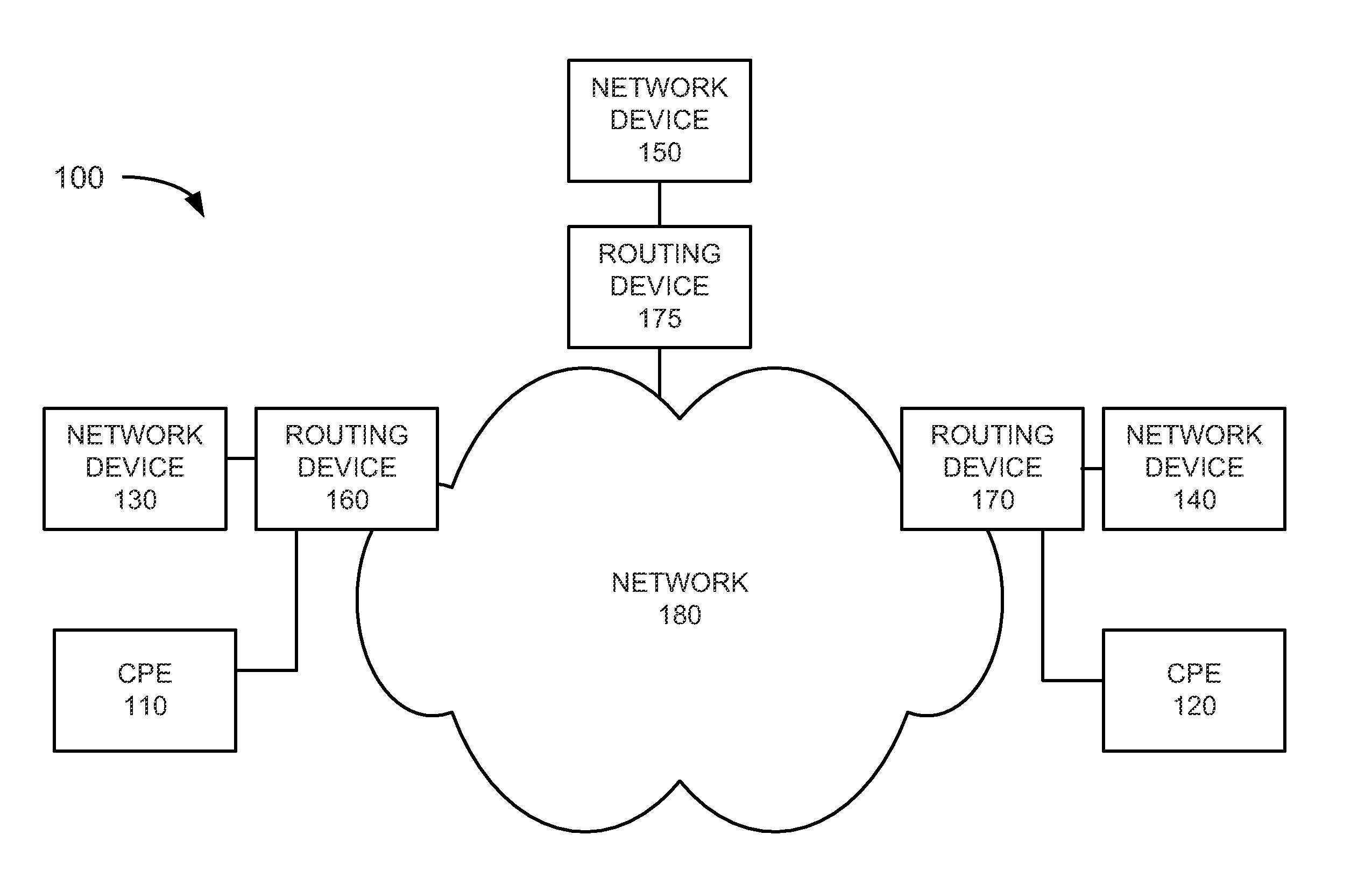
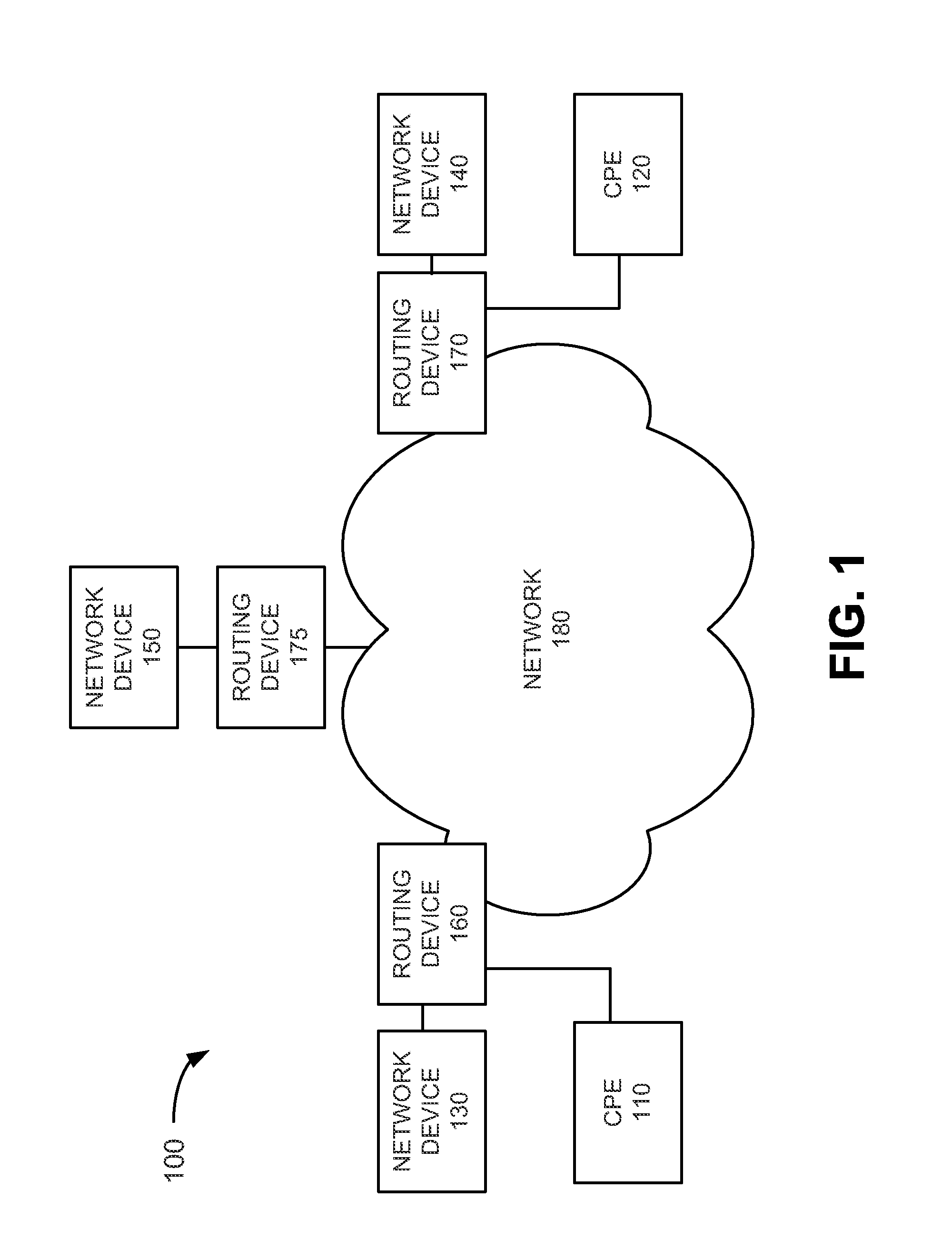
[0010]Embodiments described herein relate to a network test environment that provides for testing network parameters, such as latency, jitter, packet loss, reorder or sequencing, and Mean Opinion Score (MOS), among others. The test architecture may include a master control device that communicates with other test devices to control the testing. In some instances, backup (e.g., non-master) control devices may provide control in the event that the master control device experiences problems. The testing may also use virtual local area network (VLAN), asynchronous transfer mode (ATM), frame relay (FR), multi-protocol label switching (MPLS), or any other technology to enable point-to-point (e.g., network device to network device) testing to be accompli...


PUM


Abstract

A method may include receiving, at a first network device, a test initiation message from a control device, wherein the test initiation message includes at least an identification of a second network device. The method may further include retrieving the identification of the second network device from the test initiation message and generating test data including at least source information associated with the first network device, destination information associated with the second network device, and timestamp information associated with a time at which the test data is generated. In addition, the method may include transmitting the test data to the second network device via a data network under test and receiving return test data from the second network device. Further, the method may include generating performance information based on the return test data received from the second network device.

Description

BACKGROUND INFORMATION[0001]Processing and routing data, calls, etc., in a network has become increasingly complex due to increased overall traffic and customer bandwidth requirements. In some instances, a customer may enter into a service level agreement (SLA) with a provider that guarantees the customer an agreed level of service. As a result, a provider may test network conditions to determine whether the terms of the SLA are met. For example, a service provider may generate and route test traffic at various times to determine performance metrics related to the SLA.BRIEF DESCRIPTION OF THE DRAWINGS[0002]FIG. 1 illustrates an exemplary network in which systems and methods described herein may be implemented;[0003]FIG. 2 illustrates an exemplary configuration of components implemented in the network devices of FIG. 1;[0004]FIG. 3 illustrates another exemplary network in which systems and methods described herein may be implemented;[0005]FIG. 4 is a flowchart of an exemplary process...

Claims


Application Information

Patent Timeline
IPC IPC(8): G06F19/00
CPCH04L12/2697H04L43/50H04L43/106H04L43/08
Inventor MUCHA, DANIEL E.MOCZYGEMBA, RICHARDJALIL, LUAY
Owner VERIZON PATENT & LICENSING INC
Why Eureka
Try Eureka