Capacitive divider device, voltage sensor, trip device module and electrical protection apparatus provided with such a device

a technology of trip device and capacitive divider, which is applied in the direction of fixed capacitor details, fixed capacitors, instruments, etc., can solve the problem of relatively high output impedan

Active Publication Date: 2010-06-24
SCHNEIDER ELECTRIC IND SAS
View PDF4 Cites 19 Cited by
  • Summary
  • Abstract
  • Description
  • Claims
  • Application Information

AI Technical Summary

Benefits of technology

[0006]The object of the invention is to remedy the technical problems of capacitive dividers of the prior art by proposing a capacitive divider device designed to attenuate an input voltage, said device comprising electrodes formed on different levels of a multilayer structure separated by insulating layers, said electrodes including a first and second main electrode to apply said input voltage and a common electrode to supply an attenuated voltage from said input voltage, said capacitive divider being characterized in that said first and second main electrodes are formed on one and the same level of said structure, the common electrode being formed on another level of said structure, said common electrode being arranged so as to form a first capacitive unit with the first main electrode and to form a second capacitive unit with the second main electrode, that said device comprises at least a first auxiliary electrode formed on yet another level of the multilayer structure and arranged to form a first auxiliary capacitive unit with the common electrode, and that said auxiliary electrode and the second main electrode extend towards one side of the multilayer structure so as to electrically connect said auxiliary electrode to the second main electrode via a linear conductor.

Problems solved by technology

One drawback of prior-art capacitive dividers is that they present a relatively high output impedance.

Method used


Image

  • Capacitive divider device, voltage sensor, trip device module and electrical protection apparatus provided with such a device
  • Capacitive divider device, voltage sensor, trip device module and electrical protection apparatus provided with such a device
  • Capacitive divider device, voltage sensor, trip device module and electrical protection apparatus provided with such a device

Examples


Embodiment Construction

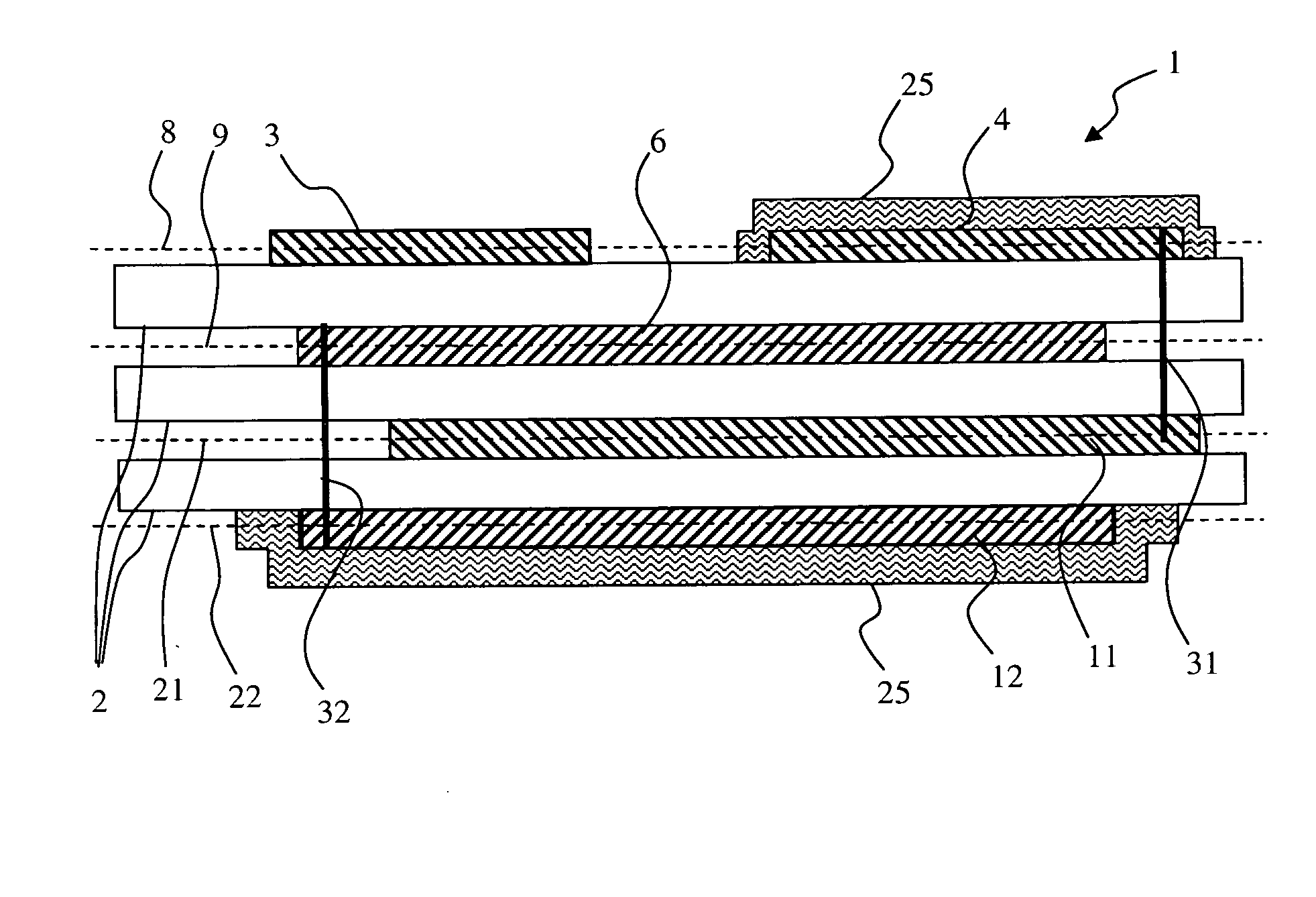
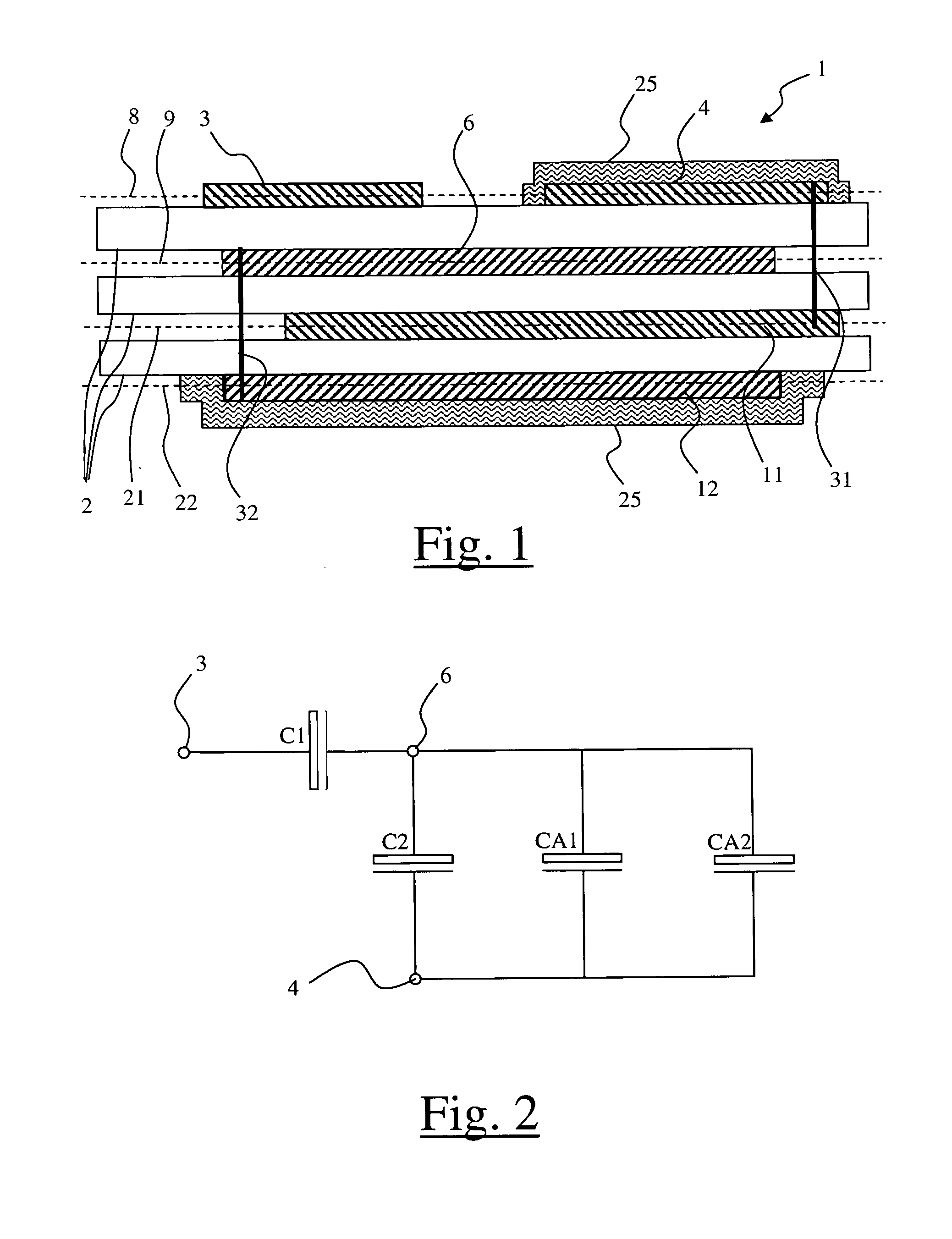
[0030]With reference to FIG. 1, the capacitive divider is formed in a multilayer structure 1 comprising electrodes on several levels separated by insulating layers 2. The electrodes of the capacitive divider include a first main electrode 3 and a second main electrode 4 enabling an input voltage VE to be applied. The first and second main electrodes can also be respectively referred to as potential electrode and measurement electrode. Multilayer structure 1 also comprises a common electrode 6 to supply an attenuated voltage VS from input voltage VE. More precisely, the attenuated voltage is generally supplied between common electrode 6 and second electrode 4.

[0031]As can be seen in FIG. 1, first and second main electrodes 3, 4 are formed on the same level 8 of multilayer structure 1. Common electrode 6 is for its part formed on another level 9 of the multilayer structure.

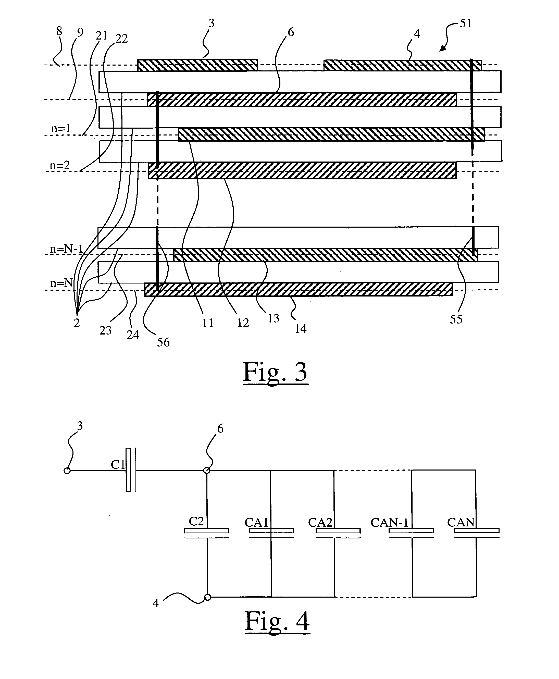
[0032]As can be seen in FIG. 2, common electrode 6 is arranged so as to form a first capacitive unit C1 with firs...


PUM


Abstract

A multilayer capacitive divider comprising a first and second main electrode formed on the same level to apply an input voltage, and a common electrode formed on another level to supply an attenuated voltage, said device comprising at least a first auxiliary electrode formed on yet another level, said electrodes being arranged so as to form capacitive units, said auxiliary electrode extending towards a side of said device towards which the second main electrode is arranged so as to connect said auxiliary electrode to the second main electrode by means of a linear conductor.A voltage sensor, a trip device module and an electrical protection apparatus provided with one such device.

Description

BACKGROUND OF THE INVENTION[0001]The invention is in the field of capacitors formed in a multilayer structure, and in particular of capacitive dividers formed in such a structure.[0002]The invention relates to a capacitive divider device designed to attenuate an input voltage, said device comprising electrodes formed on different levels of a multilayer structure separated by insulating layers, said electrodes including a first and second main electrode to apply said input voltage, and a common electrode to supply an attenuated voltage from said input voltage.[0003]The invention also relates to a voltage sensor, a trip device module and an electrical protection apparatus provided with such a capacitive divider device.STATE OF THE ART[0004]European Patent application EP 0631144 describes a voltage sensor comprising two capacitive divider networks equipped with common terminals designed to provide an attenuated voltage, said networks comprising capacitors connected in series and integr...

Claims


Application Information

Patent Timeline
Patent Type & Authority Applications(United States)
IPC IPC(8): G01R27/26H01G4/30H02H9/02
CPCG01R15/06H01G4/232H01G4/30H01L2924/0002H01L2924/00
Inventor MOLITON, VIVIENVINCENT, FRANCOIS
Owner SCHNEIDER ELECTRIC IND SAS
Why Eureka
Try Eureka