Image projection device and rear projection type display device

a technology of image projection device and display device, which is applied in the direction of projectors, color television details, instruments, etc., can solve the problems of damage to the retina and dangerous to directly observe the laser light from the image projection device, so as to enhance the safety and enhance the safety with a required minimum device scale

Inactive Publication Date: 2010-06-24
PANASONIC CORP
View PDF4 Cites 15 Cited by
  • Summary
  • Abstract
  • Description
  • Claims
  • Application Information

AI Technical Summary

Benefits of technology

[0027]According to Claim 1 of the present invention, there is provided an image projection device comprising: an image projection unit comprising a laser light source for emitting laser light, one-dimensional or two-dimensional spatial light modulation element for spatially modulating the divergent laser light emitted from the laser light source, and a projection lens for projecting the laser light that is spatially modulated by the one-dimensional or two-dimensional light modulation element onto a screen to form an image of the one-dimensional or two-dimensional spatial light modulation element; and n pieces of folding mirrors including an n-th folding mirror (n: an integer not less than 1) for reflecting the laser light emitted from the image projection unit toward the screen, said folding mirrors being provided between the image projection unit and the screen; wherein a distance between the n-th folding mirror and the image projection unit is larger than a class 2 nominal ocular hazard distance of the image projection unit. Therefore, when the image projection unit is observed from a position onto which the image is projected, observation is carried out from a position apart by a distance larger than the class 2 nominal ocular hazard distance, thereby enhancing the safety.
[0028]According to Claim 2 of the present invention, in the image projection device defined in Claim 1, the class 2 nominal ocular hazard distance of the image projection unit is a distance L by which a light output power emitted from the projection lens with a solid angle of 38.4 / (L×L) is 1 mW. Therefore, when the image projection unit is observed from a position onto which the image is projected, observation is carried out from a position apart by a distance larger than the class 2 nominal ocular hazard distance, thereby enhancing the safety with a required minimum device scale.
[0029]According to Claim 3 of the present invention, the image projection device defined in Claim 1 further includes a frame surrounding an optical path between the image projection unit and the n-th folding mirror. Therefore, it becomes difficult for a person to observe the laser light with his head being put in a region where the laser light is dangerous to human eyes, thereby further enhancing the safety.
[0030]According to Claim 4 of the present invention, in the image projection device defined in Claim 1, at least one of the n pieces of folding mirrors has a convex shape. Therefore, the divergence angle of the projected light from the image projection unit can be increased, and thereby the energy of the laser light is reduced to a safety level at a short distance, resulting in further miniaturization of the device.
[0031]According to Claim 5 of the present invention, an image projection device comprising: an image projection unit comprising a laser light source for emitting laser light, one-dimensional or two-dimensional spatial light modulation element for spatially modulating the divergent laser light emitted from the laser light source, and a projection lens for projecting the laser light that is spatially modulated by the one-dimensional or two-dimensional light modulation element onto a screen to form an image of the one-dimensional or two-dimensional spatial light modulation element; and a restriction plate for restricting approach of a person to the laser light path, which is provided between the image projection unit and the screen; wherein a distance between the restriction plate and the image projection unit is larger than a class 2 nominal ocular hazard distance of the image projection unit. Therefore, approach of a person to the laser light path can be restricted, thereby enhancing the safety.

Problems solved by technology

Therefore, when the laser light enters into human eye, it converges to a point on retina, and might damage the retina.
Further, in a case where laser light from an image projection device is projected on a screen and the laser light divergently reflected at the screen is observed, it might be dangerous to directly observe the laser light from the image projection device although the divergently-reflected light is safe.

Method used


Image

  • Image projection device and rear projection type display device
  • Image projection device and rear projection type display device
  • Image projection device and rear projection type display device

Examples


embodiment 1

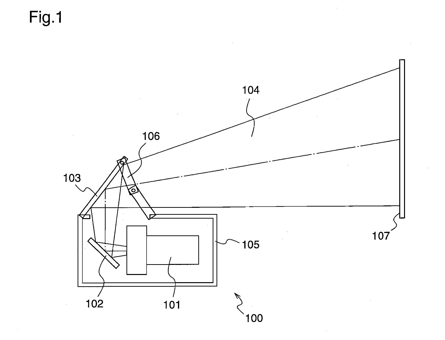
[0087]FIG. 1 is a configuration diagram of an image projection device 100 according to a first embodiment of the present invention.

[0088]In FIG. 1, the image projection device 100 comprises an image projection means 101 for projecting laser light, a first folding mirror 102 for initially folding the laser light emitted from the image projection means 101, a second folding mirror 103 for reflecting the laser light emitted from a projection lens onto a screen through the first folding mirror 102, a foldable holding frame 106, and a casing 105.

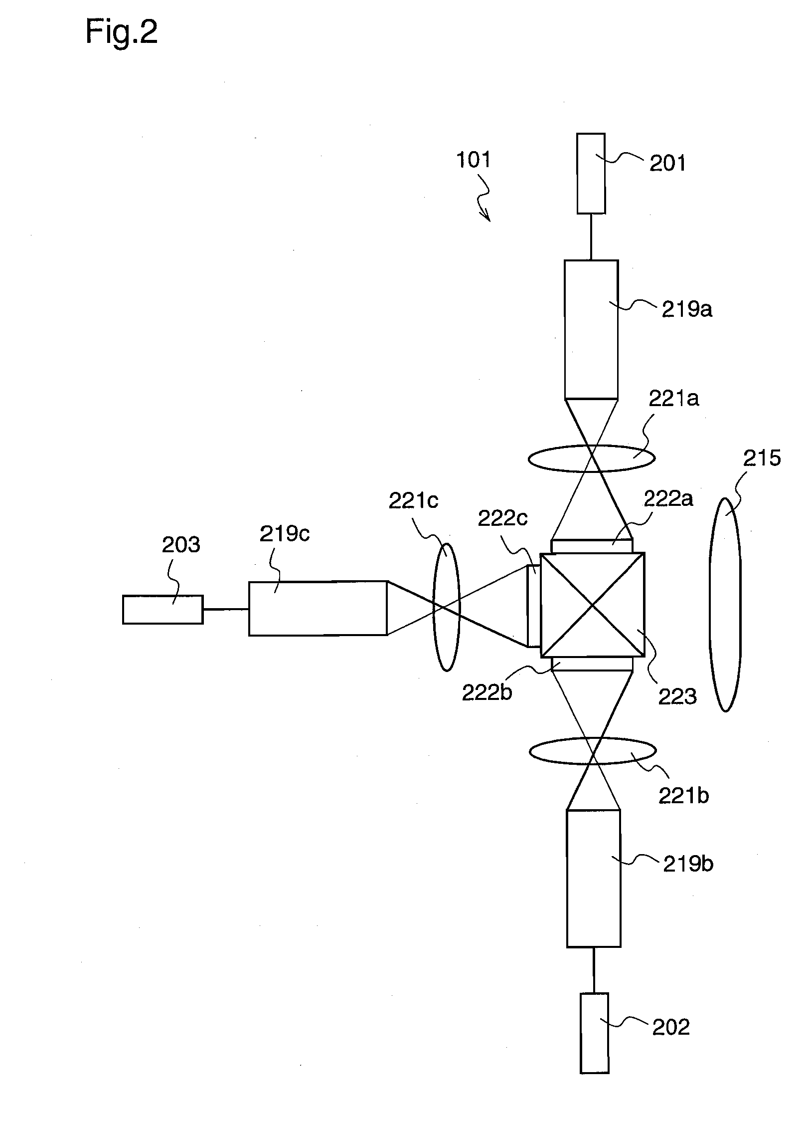
[0089]The image projection means 101 comprises, preferably, a laser light source, a two-dimensional light modulation element such as a liquid crystal panel or a micromirror array, and a projection lens. Alternatively, the image projection means 101 may comprise a laser light source, a one-dimensional light modulation element, a condenser lens, and a light scanning element.

[0090]Next, the image projection means 101 which performs spatial light mod...

embodiment 2

[0110]FIG. 6 is a configuration diagram of an image projection device according to a second embodiment of the present invention, and the same elements as those shown in FIG. 1 are given the same reference numerals to omit the description thereof. Further, in this second embodiment, the image projection means 101 adopts a one-dimensional or two-dimensional spatial light modulation element, and has the same construction as that shown in FIG. 2 or 3, and therefore, repeated description is not necessary.

[0111]The image projection device 600 according to the second embodiment is different from the first embodiment in that it is provided with a restriction plate 601 instead of the holding frame 106 of the first embodiment.

[0112]In FIG. 6, the restriction plate 601 preferably comprises a transparent acrylic plate having a high transmissivity to projected light 104, and is larger than a sectional area of beam of the projected light 104. Further, the restriction plate 601 holds the second fo...

embodiment 3

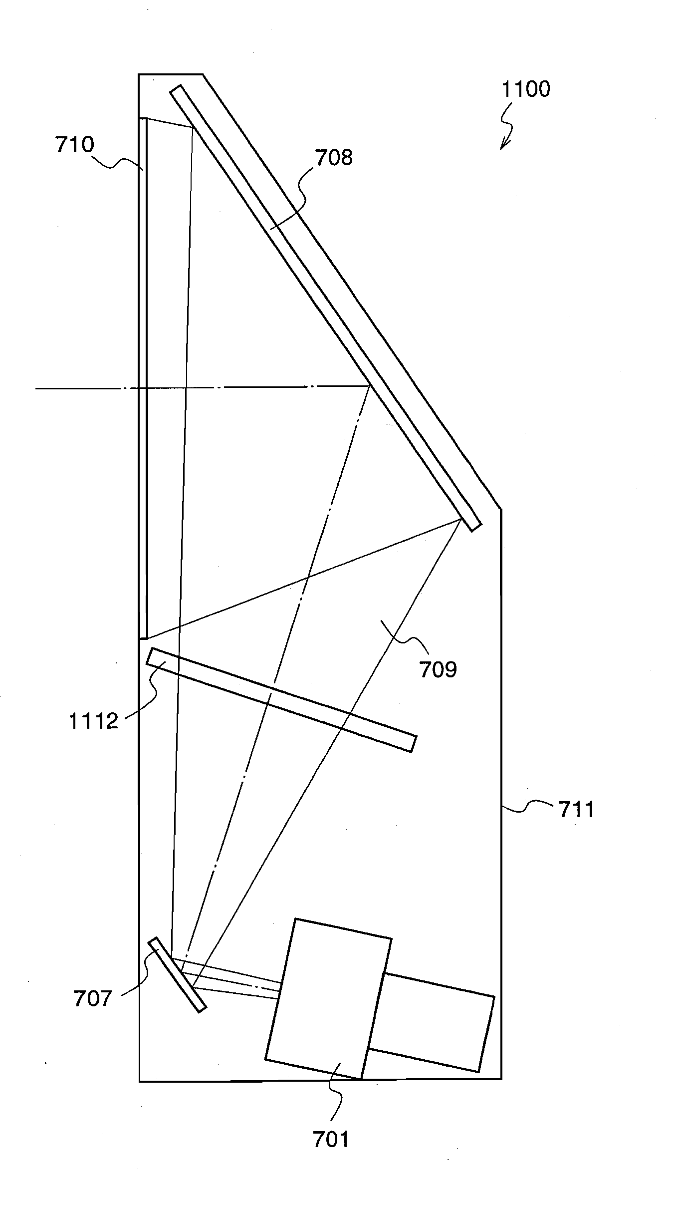
[0123]FIG. 7 is a configuration diagram of a rear projection type display device according to a third embodiment of the present invention.

[0124]With reference to FIG. 7, the rear projection type display device 700 of the third embodiment has a laser light emitting facet facing a screen 710, and comprises an image projection means 701 for projecting laser light, a first folding mirror 707 for folding the laser light emitted from the image projection means 701 toward the image projection means 701, a second folding mirror 708 for reflecting the laser light reflected by the first folding mirror 707, toward the screen 710 to emit the laser light from the image projection means 701 to the screen 710, the screen 710 for displaying an image by the laser light from the image projection means 701, and a casing 711 containing these elements.

[0125]The image projection means 701 according to the third embodiment preferably comprises a laser light source, a two-dimensional light modulation eleme...


PUM


Abstract

An image projection device comprising an image projection means (101) for projecting an image by laser light by using a one-dimensional or two-dimensional spatial light modulation element, a first folding mirror (102) for initially folding the laser light emitted from the image projection means (101), and a second folding mirror (103) for reflecting the laser light emitted from the image projection means (101) to a screen (107) through the first folding mirror (102), wherein a distance between the second folding mirror (103) and the image projection means (101) is made larger than a distance L by which a light output power emitted from the projection lens of the image projection means (101) with a solid angle of 38.4 / (L×L) is less than 1 mW. Therefore, even when a person observes the image projection device (100) from a position onto which an image is projected, the person is in an area where safety is ensured, thereby enhancing the safety.

Description

TECHNICAL FIELD[0001]The present invention relates to an image projection device and a rear projection type display device for projecting an image using laser light.BACKGROUND ART[0002]An image projection device and a rear projection type display device have been known as large-screen display devices. While a high-pressure mercury lamp has conventionally been used as a light source, development of an image projection device using laser lights of three primary colors has recently been progressed because of its excellent color reproducibility and low power consumption. On the other hand, laser light is monochromatic light, and light having a coherent wavefront. Therefore, when the laser light enters into human eye, it converges to a point on retina, and might damage the retina. Accordingly, products using lasers are classified according to International Standard IEC60825 or JIS C6802:2005 in Japan, and guidelines to be maintained by manufacturers and users are provided for each class ...

Claims


Application Information

Patent Timeline
Patent Type & Authority Applications(United States)
IPC IPC(8): G03B21/28
CPCG03B21/10G03B21/28H04N9/3197H04N9/3141H04N9/3161H04N9/3129
Inventor ITOH, TATSUOYAMAMOTO, KAZUHISA
Owner PANASONIC CORP
Why Eureka
Try Eureka