Ultrasonic spindle system

Inactive Publication Date: 2010-06-24
KUBOTA OSAMU +2
View PDF7 Cites 316 Cited by
  • Summary
  • Abstract
  • Description
  • Claims
  • Application Information

AI Technical Summary

Benefits of technology

[0007]The present invention was made in view of the situations described above and was intended to provide an ultrasonic spindle system which enables a stable supply of ele

Problems solved by technology

In a conventional configuration like one that has been described above, however, since the slip ring and the feeding brush are kept in contact with each other at all times, they wear and are damaged strongly, and because of this, in addition to problems that the replacement of feeding brushes occurs

Method used


Image

  • Ultrasonic spindle system
  • Ultrasonic spindle system
  • Ultrasonic spindle system

Examples


Embodiment Construction

[0014]Hereinafter, an embodiment of the invention will be described by reference to FIGS. 1 to 3.

[0015]Note that members and arrangements which will be described below are not such as to limit the invention but can be modified variously within the spirit and scope of the invention.

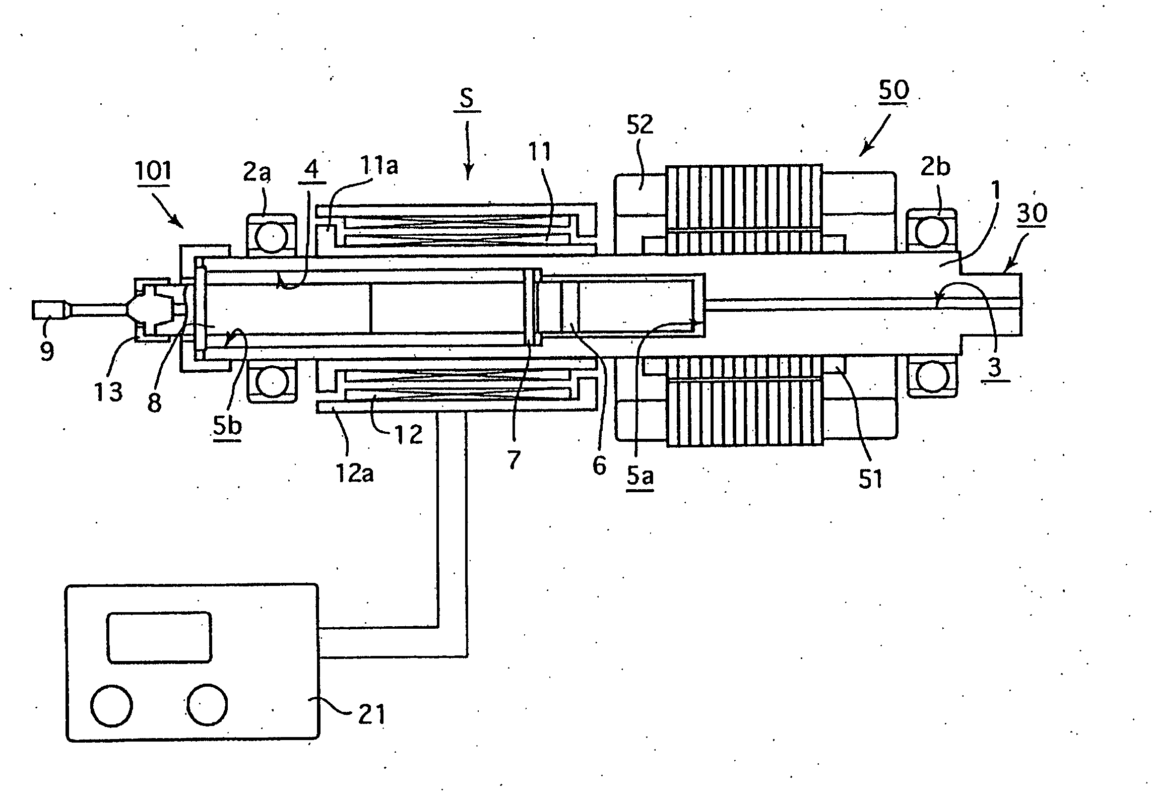
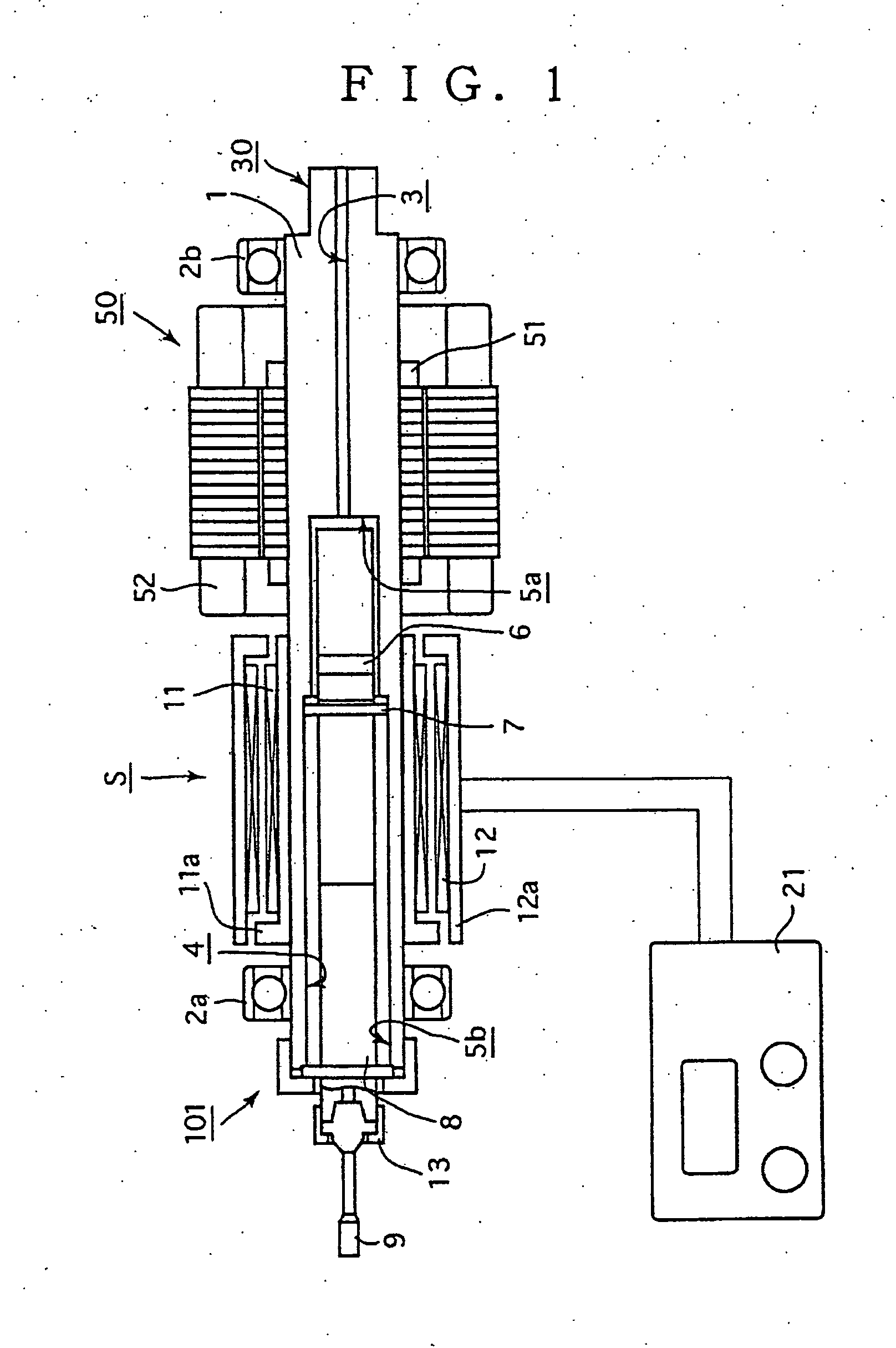
[0016]Firstly, referring to FIG. 1, a configuration example of an ultrasonic spindle system according to an embodiment of the invention will be described.

[0017]FIG. 1 is such as to show, in particular, the configuration of a spindle 101 which constitutes a main part of an ultrasonic spindle system S of the embodiment of the invention and the vicinity thereof and the spindle 101 has a shaft 30 which is rotatably supported by bearings 2a, 2b and a high frequency motor 50 for rotating the shaft 30, and is configured such that a transducer 6, a horn 8 and the like which constitutes an ultrasonic generator are provided on the shaft 30 as will be described later, and a tool grasping portion 13 for securely grasp...


PUM

PropertyMeasurementUnit
Circumferenceaaaaaaaaaa
Electric propertiesaaaaaaaaaa
Frictionaaaaaaaaaa

Abstract

It is possible to stably supply an electric signal to an ultrasonic generation element without causing friction or damage on parts or without requiring periodical parts exchange. A reception coil (11) connected to a vibrator (6) is wound on the outer circumference of a housing (1) constituting a shaft (30) of a machining spindle (101). The reception coil (11) is surrounded coaxially by a transmission coil (12) at an appropriate interval. A predetermined electric signal outputted from an ultrasonic drive device (21) for driving the vibrator (6) is applied to the transmission coil (12). The predetermined electric signal may be applied to the vibrator (6) via the reception coil (11) by electromagnetic induction between the transmission coil (12) and the reception coil (11).

Description

BACKGROUND OF THE INVENTION[0001]1. Field of the Invention[0002]The present invention relates to an ultrasonic spindle system and more particularly to an ultrasonic spindle system in which enhancement in reliability in supplying electric power to an ultrasonic generator and simplification in construction are attempted to be realized.[0003]2. Description of the Related Art[0004]In recent years, various machine tools which employ a machining method referred to as an ultrasonic milling in which a machining operation is performed while imparting ultrasonic vibrations in an axial direction of the tool have been proposed due to enhancement in machining accuracy and smooth discharge of chips being realized (for example, refer to Patent Document No. 1).[0005]In the system in which the ultrasonic milling is performed, a configuration is adopted in which a generator for generating ultrasonic waves is mounted in the vicinity of a rotary tool for rotation together with the tool. In addition, al...

Claims


Application Information

Patent Timeline
IPC IPC(8): H04R9/06
CPCB23B29/125B23Q2230/004B23B2270/10B23B37/00B06B1/02
Inventor KUBOTA, OSAMUYUI, TAKAYUKIHURUKAWA, HIDEO
Owner KUBOTA OSAMU
Why Eureka
Try Eureka