Method of controlling fluid flow in microfluidic device and microfluidic analysis apparatus

a microfluidic device and microfluidic analysis technology, which is applied in the direction of laboratory glassware, instruments, suspensions, etc., can solve the problems of inconvenient testing of analyte concentration, inability to accurately quantify the concentration of analyte, and pores formed in the membrane, so as to achieve simple and accurate control of fluid flow

Inactive Publication Date: 2010-06-24
ELECTRONICS & TELECOMM RES INST
View PDF3 Cites 13 Cited by
  • Summary
  • Abstract
  • Description
  • Claims
  • Application Information

AI Technical Summary

Benefits of technology

[0006]The present invention provides a method of controlling a fluid flow...

Problems solved by technology

Biochips realized using membranes are disadvantageous for adjusting the flow of microfluid.
However, uniformity of sizes of the pores formed in the membranes is below the level required for an accurate test.
As a result, since it is impossible to adjust a microfluidic flow velocity in the membrane, the biochip realized using the membrane is not suitable for testing to accurately quantify the concentration of an analyte.
There are many limitations in a typical biochip field in which a constant transfer velocity of the fluid in a microchannel, a constant reaction time in a reaction region, and a transfer stopping ability of fluid are necessary for quantifying analytes.
Biochips using only capillary action are limited in that only the configuration and size of a channel are adjusted to accurately control fluid flow.
Although a method in which an inner wall of the channel is surface-treated to have a hydrophilic property or a hydrophobic property to control the fluid was attempted, it is difficult to realize a biochip having a function that stops the fluid at a...

Method used


Image

  • Method of controlling fluid flow in microfluidic device and microfluidic analysis apparatus
  • Method of controlling fluid flow in microfluidic device and microfluidic analysis apparatus
  • Method of controlling fluid flow in microfluidic device and microfluidic analysis apparatus

Examples


Embodiment Construction

[0025]Preferred embodiments of the present invention will be described below in more detail with reference to the accompanying drawings. The present invention may, however, be embodied in different forms and should not be construed as limited to the embodiments set forth herein. Rather, these embodiments are provided so that this disclosure will be thorough and complete, and will fully convey the scope of the present invention to those skilled in the art.

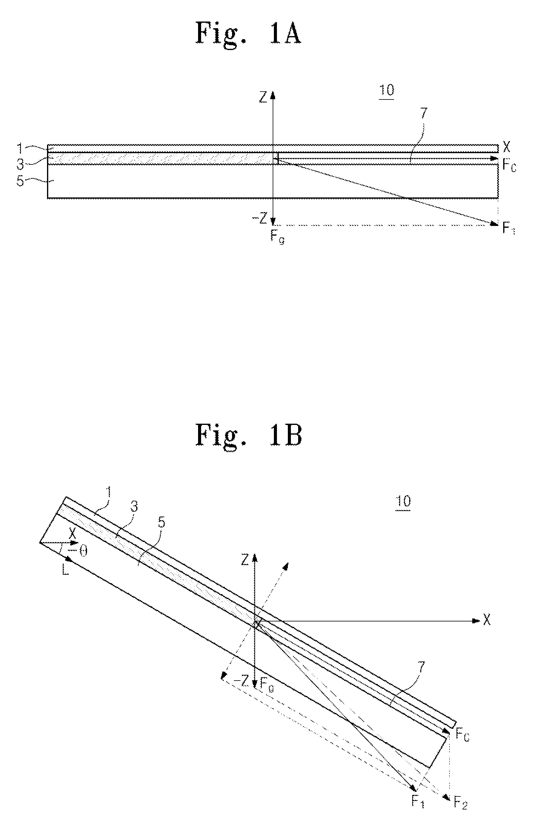
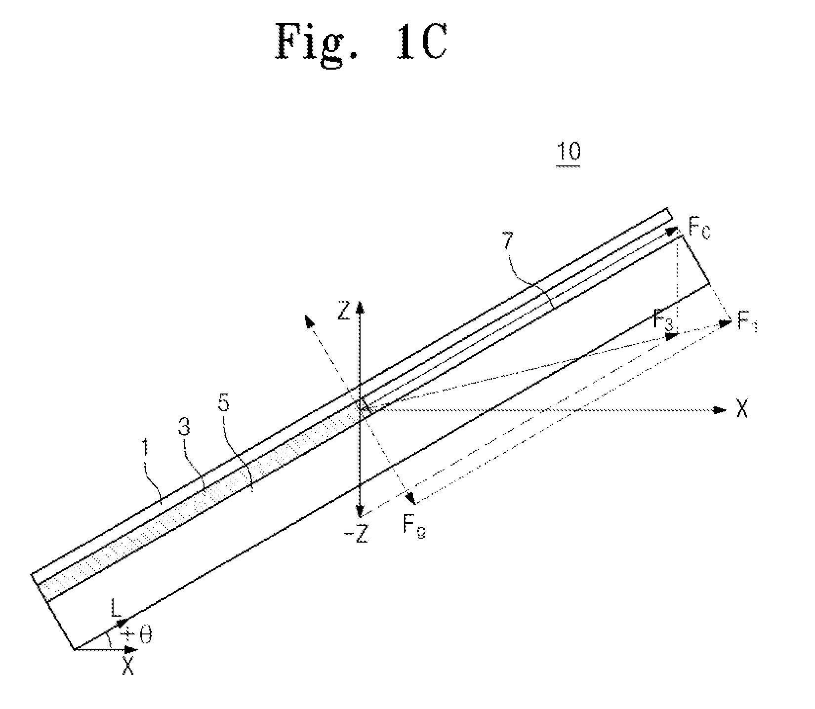
[0026]FIGS. 1A, 1B, and 1C are cross-sectional views illustrating force vectors acting on a microfluid according to inclination of a microfluidic device.

[0027]Referring to FIG. 1A, a microfluidic device 10 includes an upper plate 1, a lower plate 5 facing the upper plate 1, and a fluid 3 flowing along a flow path 7 defined by the upper plate 1 and the lower plate 5. The microfluidic device 10 is disposed in parallel to a horizontal direction (X-axis). A force F1 applied to the fluid 3 may be expressed as a resultant force of a capil...


PUM


Abstract

Provided are methods of controlling a fluid flow in a microfluidic device and a microfluidic analysis apparatus. According to the method, an inclination of the microfluidic device with respect to a horizontal direction can be adjusted to simply and accurately control a fluid flow in the microfluidic device. Thus, a fluid conveyance can be completely controlled, and an inspection can be performed using only a small amount of sample. In addition, the method of controlling the fluid flow in the microfluidic device can be manually performed by a user. Thus, since a power is not required, the method of controlling the fluid flow in the microfluidic device can be economical and simple. The microfluidic analysis apparatus includes an inclination operation unit for causing an inclination change of a receiving part of the microfluidic device with respect to a horizontal plane and an inclination control part for controlling an operation of the inclination operation unit to simply and accurately control the fluid flow, thereby to accurately analyze the fluid.

Description

CROSS-REFERENCE TO RELATED APPLICATIONS[0001]This U.S. non-provisional patent application claims priority under 35 U.S.C. §119 of Korean Patent Application No. 10-2008-0131856, filed on Dec. 23, 2008, the entire contents of which are hereby incorporated by reference.BACKGROUND OF THE INVENTION[0002]The present invention disclosed herein relates to a method of controlling a fluid flow in a microfluidic device and a microfluidic analysis apparatus.[0003]Typical biochips quickly detect analytes such as biomaterials or environmental materials using membranes or hygroscopic papers. For example, biochips may be used for pregnancy diagnostic apparatuses, apparatuses for measuring hormones such as human chorionic gonadotropin (HCG), and alpha fetoprotein (AFP) (this is used as a liver cancer biomarker) measurements, which are currently commercialized. Biochips realized using membranes are disadvantageous for adjusting the flow of microfluid. The membranes may be formed of a polymeric materi...

Claims


Application Information

Patent Timeline
IPC IPC(8): G01N35/10G01N33/00
CPCB01L3/50273B01L9/527Y10T436/11G01N35/08B01L2400/0457G01N30/26G01N33/563G01N33/553
Inventor SHIN, DONG-HOJEONG, MINSUKSONG, KYU HOKIM, HYEYOONJEON, JUHYUNJUNG, MOON YOUNPARK, SEON HEE
Owner ELECTRONICS & TELECOMM RES INST
Why Eureka
Try Eureka