Inverted dispensing system and apparatus

a dispensing system and inverted technology, applied in liquid transferring devices, pliable tubular containers, transportation and packaging, etc., can solve the problems of creating safety hazards, unsightly clutter, and spilling of container contents, and achieve the effect of minimizing the risk of spillag

Inactive Publication Date: 2007-08-28
INNOVATION & DESIGN
View PDF44 Cites 25 Cited by
  • Summary
  • Abstract
  • Description
  • Claims
  • Application Information

AI Technical Summary

Benefits of technology

[0009]The present subject matter recognizes and addresses the above-briefly discussed drawbacks, and others, of the prior art dispensing systems. Accordingly, one broad aspect of the present subject matter is to provide an improved dispensing system. A further present general object is to provide a dispensing system which can be attached to a shower wall. A still further present more specific object w

Problems solved by technology

The designs of such containers create several different drawbacks and problems from storage to dispensing.
Such plastic containers litter the bathroom shower area of many households creating unsightly clutter.
Often, the containers are not readily accessible within the shower area which can lead to the spilling of the container's content.
Such clutter, inaccessibility and possible spills can create safety hazards within the shower area, as well as create waste and other disadvantages.
The upright containers also create a dispensing issue due to the configuration of the container in which it is contained and/or the potentially viscous nature of the content being dispensed.
The more the fluid in the container is used, the longer the distance the fluid must travel with less momentum due to the decrease in the mass of the fluid after each use, and the greater the effort and time required to dispense what fluid remains in the container.
Other devices and containers have tried to address

Method used


Image

  • Inverted dispensing system and apparatus
  • Inverted dispensing system and apparatus
  • Inverted dispensing system and apparatus

Examples


Embodiment Construction

[0032]Reference will now be made in detail to the presently preferred embodiments of the present subject matter, one or more examples of which are shown in the Figures. Each example is provided to explain the subject matter, and not as a limitation of the subject matter. In fact, features illustrated or described as part of one embodiment can be used with another embodiment to yield still a further embodiment. It is intended that the present subject matter cover such modifications and variations.

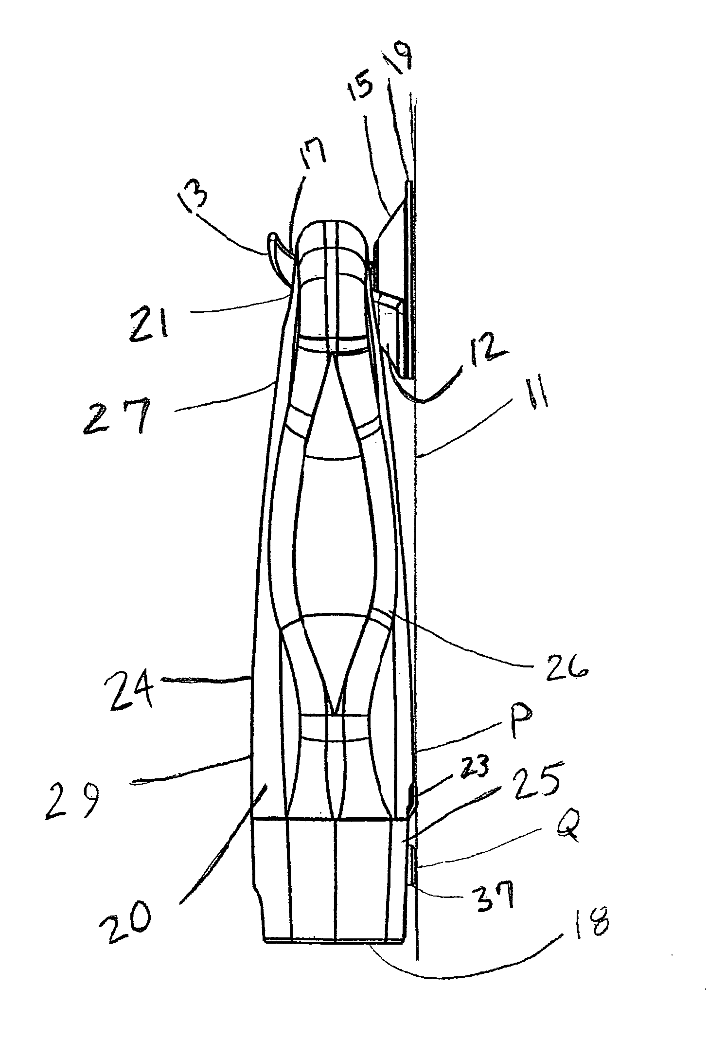
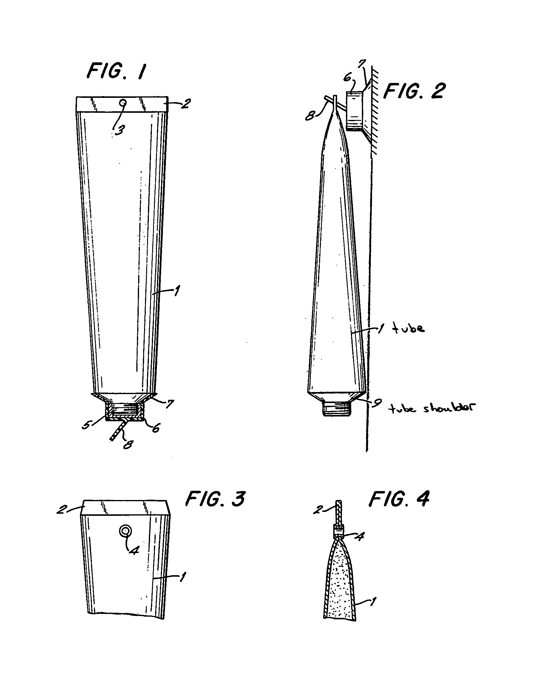
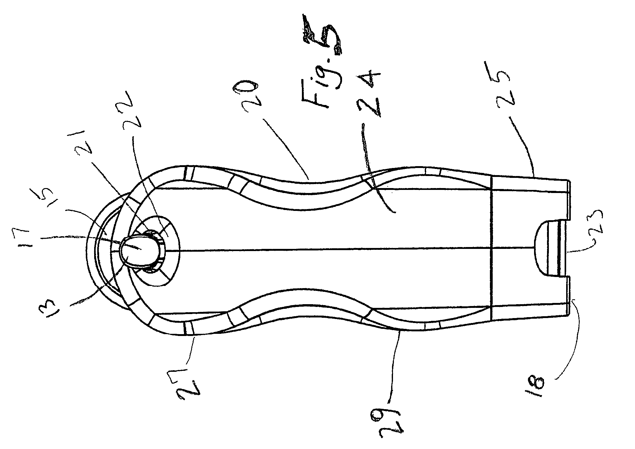
[0033]FIG. 1 shows an embodiment of a dispensing system 10 having an inverted resilient deformable container 20 and a hooking device 15 used to dispense fluids, especially fluids used in a shower environment, such as shampoos, conditioners, liquid soaps, lotions, or other fluids. The container 20 has an upper portion 27 and a lower portion 29. The upper portion 27 defines a through-hole 21 through the container 20 having through-hole walls 22. Through-hole 21 is formed such that fluid stays ...


PUM


Abstract

A disposable inverted dispensing system for distributing a fluid for use in a shower is disclosed. The dispensing system includes a removable hooking device that is attachable to a surface which is exposable to moist conditions. A hook integral to the removable hooking device extends from the hooking device on a side opposite the surface when the hooking device is attached to the surface. A deformable container for containing the fluid has an upper portion and a lower portion. The upper portion defines a through-hole through the container, and the lower portion forms a container mouth through which the fluid is flowable. A dispensing valve and/or a cap is disposed over the mouth of the container for controlling the flow of the fluid. The container is positionable on the hooking device with the hook extending through the through-hole formed by the upper portion of the container so that the container hangs down from the hooking device.

Description

CLAIM OF PRIORITY AND CROSS REFERENCE TO RELATED APPLICATIONS[0001]This application claims the benefit of U.S. Provisional Patent Application entitled “Shower Dispenser Bottle,” filed Apr. 16, 2003, and having Ser. No. 60 / 463,628 and U.S. Design application entitled “Suction Cup Mounted Shower Dispenser,” filed Oct. 27, 2003, and having a Ser. No. 29 / 192,586.BACKGROUND OF THE INVENTION[0002]This subject matter concerns a dispensing system for a fluid in general, and more particularly a disposable inverted dispensing system for dispensing shampoo or other liquid materials (such as soap or conditioner, or gel or lotion of any type) for use in a shower.[0003]The manufacture and sale of hair care and personal hygiene products constitutes an expansive market. As can be seen in almost any household, shampoo, conditioners, liquid soaps, and other materials represent a large portion of this market. Conventionally, such products are sold in plastic containers which stand upright with a cappi...

Claims


Application Information

Patent Timeline
IPC IPC(8): B67D5/06B65D23/00B67D7/06B65D47/20
CPCB65D23/003B65D47/2018
Inventor AWBREY, JERRY R.BROWN, MICHAEL D.
Owner INNOVATION & DESIGN
Why Eureka
Try Eureka