Eureka AIR delivers breakthrough ideas for toughest innovation challenges, trusted by R&D personnel around the world.

Indoor unit of air conditioner

a technology for air conditioners and units, applied in lighting and heating apparatus, ventilation systems, heating types, etc., can solve the problems of burdensome detachment/attachment of container boxes, especially for elderly people and women, and achieve the effects of reducing the flow resistance of air, dust transfer capability, and improving the efficiency of disposal

Active Publication Date: 2010-06-24
DAIKIN IND LTD
View PDF8 Cites 11 Cited by
  • Summary
  • Abstract
  • Description
  • Claims
  • Application Information

AI Technical Summary

Benefits of technology

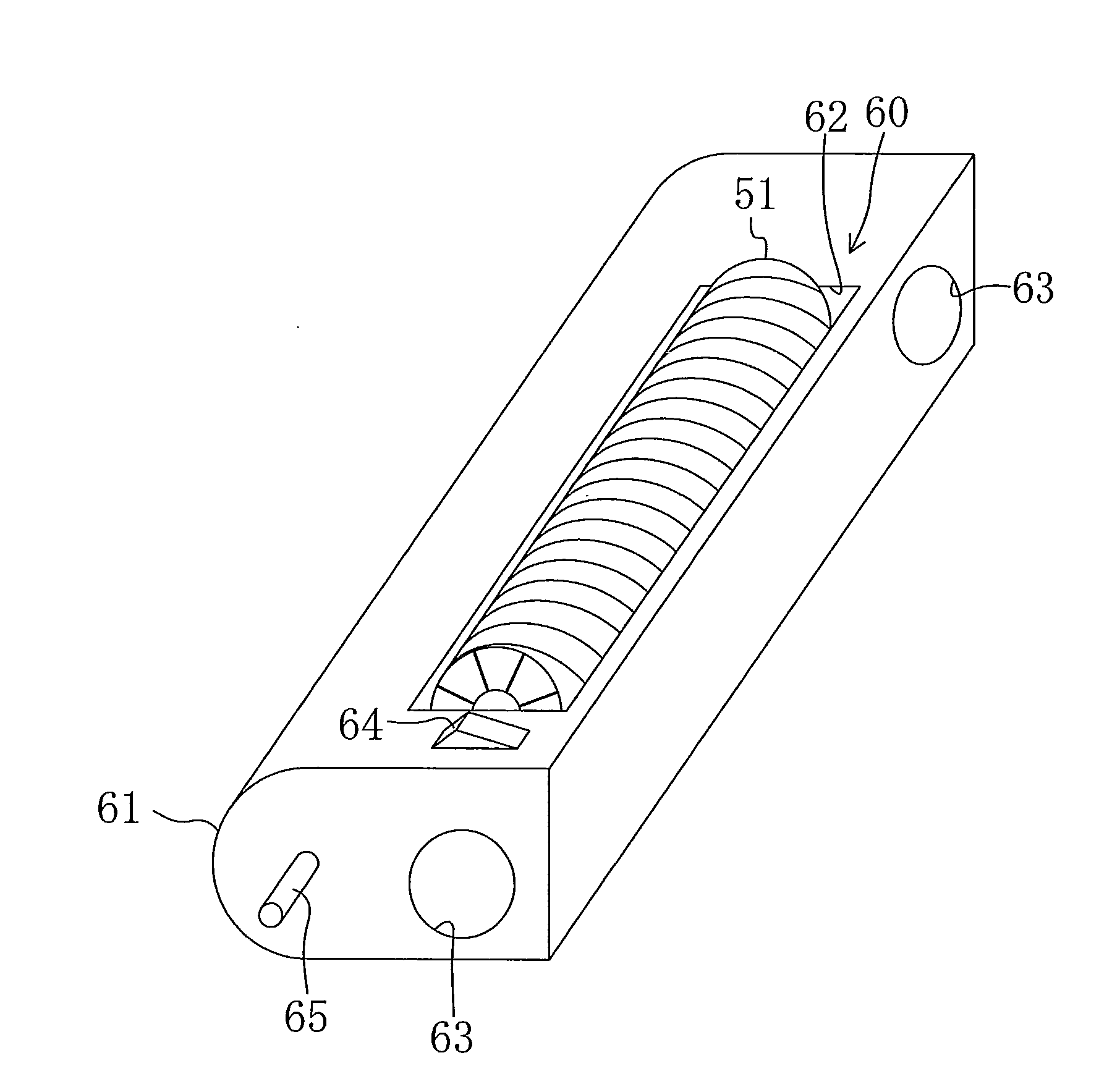
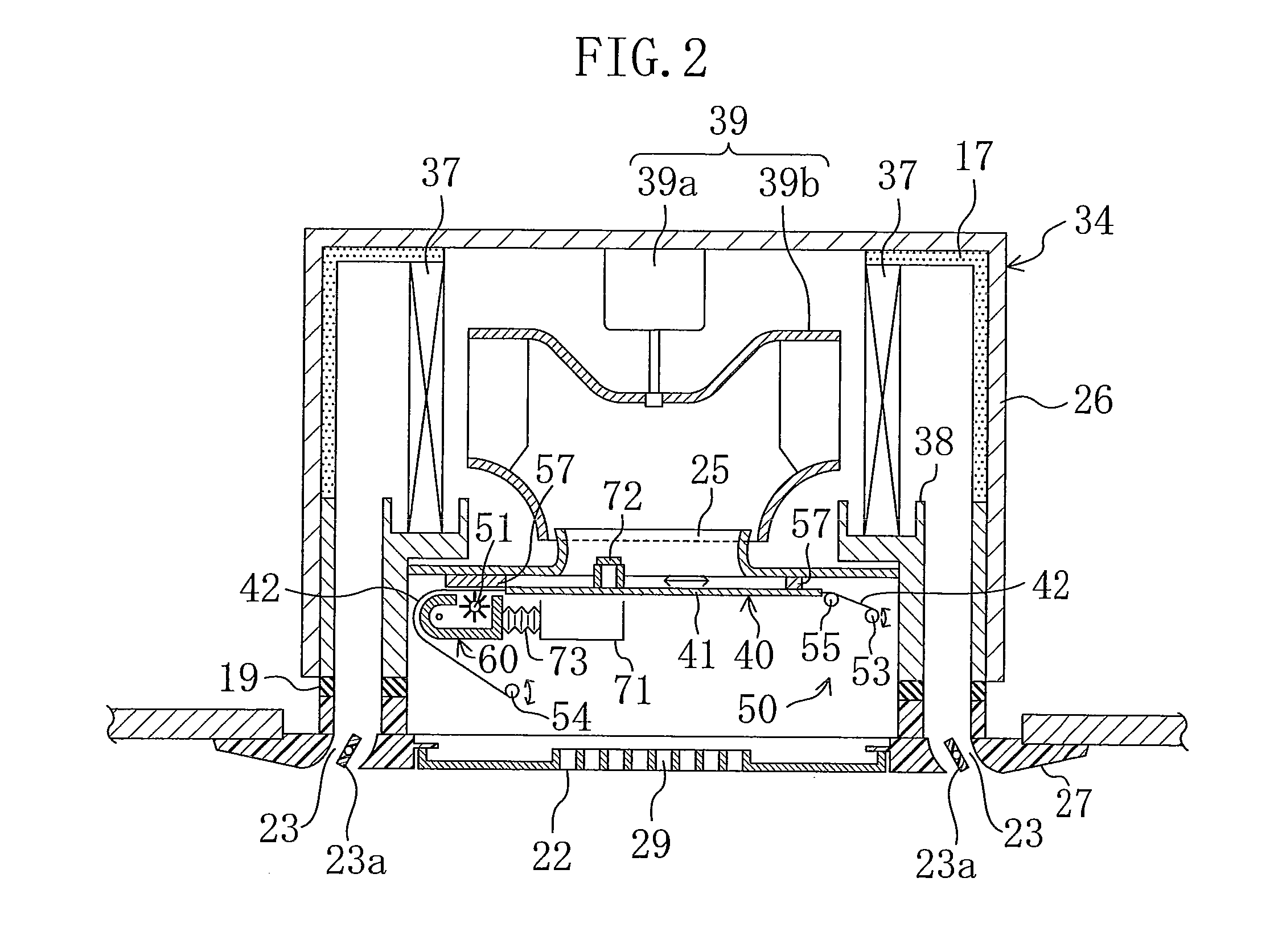
[0046]According to the present invention described above, the dust removed from the air filter (40) is transferred to a predetermined location by the air blowing from the indoor fan (39). Therefore, the removed dust can easily be transferred to the predetermined location suitable for disposal of the dust without providing another transfer means, such as a suction fan, etc. This can improve the efficiency in disposal of the dust removed from the air filter (40) without upsizing the unit.
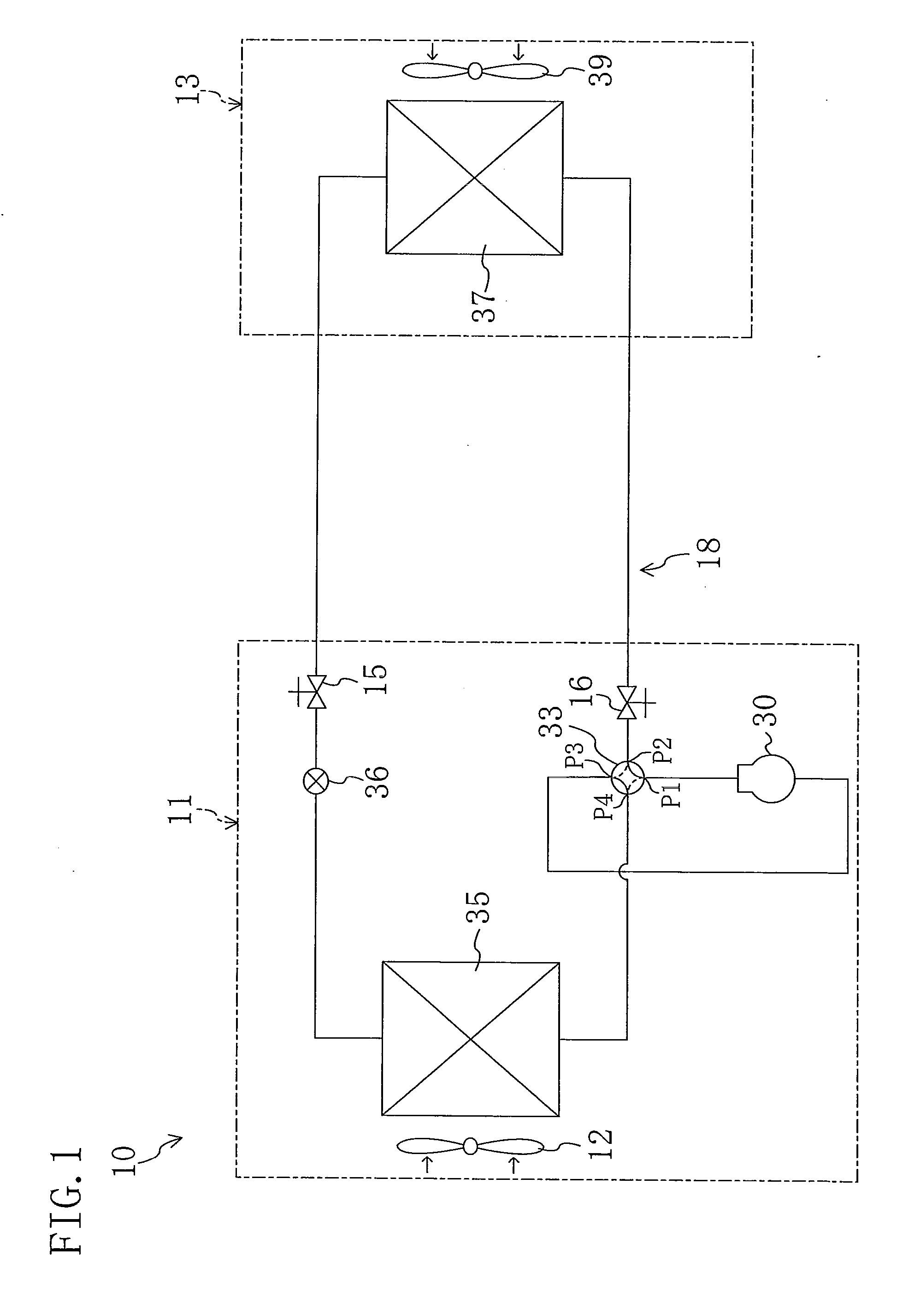
[0047]According to the second aspect of the invention, the dust removed by the dust removing means (50) is transferred by the air which is not yet supplied to the indoor heat exchanger (37). Therefore, as compared with the case where the dust is transferred by the air that has passed through the indoor heat exchanger (37), flow resistance of the air decreases, thereby ensuring dust transfer capability. Therefore, it is no longer necessary to increase the capacity of the indoor fan (39) for the dust transfer.
[0048]According to the third aspect of the invention, the dust container (60) for containing the dust removed from the air filter (40) is provided, and the air blowing from the indoor fan (39) is brought into the dust container (60). Therefore, the removed dust can temporarily be contained in the dust container (60), and then the dust is transferred in bulk. This can improve the efficiency of the dust transfer.
[0049]According to the fourth aspect of the invention, the air which is not yet supplied to the indoor heat exchanger (37) is brought into the dust container (60). For example, in cooling the room, the air before cooled in the indoor heat exchanger (37) is brought into the dust container (60), thereby preventing condensation formed by the cooled air in the dust container (160). This does not require additional measures to prevent the condensation, thereby reducing the cost.
[0050]Particularly according to the fifth aspect of the invention, the supply duct (71) and the discharge duct (74) are provided for bringing the air blowing from the indoor fan (39) into the dust container (60) for the dust transfer. This makes it possible to transfer the dust removed from the air filter (40) to the predetermined location with reliability by the air blowing from the indoor fan (39).
[0051]According to the sixth aspect of the invention, the open / close means (72) is arranged at an air inlet port of the dust transfer means (70). Opening the open / close means (72) as required in cleaning the air filter (40) makes it possible to bring the air blowing from the indoor fan (39) into the dust container (60). This can prevent wasteful supply of the air blowing from the indoor fan (39) to the dust container (60). Therefore, in normal operation, all the air blowing from the indoor fan (39) can be supplied to the indoor heat exchanger (37). This does not impair the comfortability of a person in the room.

Problems solved by technology

However, since the indoor unit of this type is generally installed at high elevations in a room, the detaching / attaching of the container box is burdensome particularly for elderly people and women.

Method used


Image

  • Indoor unit of air conditioner
  • Indoor unit of air conditioner
  • Indoor unit of air conditioner

Examples


first embodiment

Modified Example of First Embodiment

First Modified Example

[0177]A first modified example is achieved by adding an air collecting plate (91) to the damper (72) of the supply duct (71) of the first embodiment as shown in FIG. 11. Specifically, the air collecting plate (91) is a vertically oriented concave plate, and is arranged along half the circumference of an inlet of the damper (72). The air collecting plate (91) is arranged with a concave surface (91a) opposing to the direction of the air blowing from the indoor fan (39). In this modified example, the air blowing from the indoor fan (39) is reliably captured by the air collecting plate (91). Therefore, the air blowing from the indoor fan (39) easily enters (is easily brought into) the supply duct (71) from the damper (72). This increases the amount of air supplied to (brought into) the dust container (60), thereby allowing for easy discharge of the dust. As a result, the efficiency of the dust discharge (the dust transfer) improv...

second modified example

[0178]In a second modified example, the dust is transferred and contained in a dust collection box (92) placed outside the casing (34) as shown in FIG. 12. Specifically, the dust collection box (92) is attached to a side surface of the casing (34) in the space above the ceiling. The discharge duct (74) extending from the inside of the casing (34) is connected to the dust collection box (92), and the dust is transferred from the dust container (60), and is contained in the dust collection box (92). The dust collection box (92) is sufficiently larger in volume than the dust container (60). Therefore, the box can contain a larger amount of dust than the dust container (60). Specifically, since the dust container (60) is arranged below the air filter (40), i.e., near the path of the sucked air, it needs to be reduced in volume as much as possible so as not to disturb the air flow. Therefore, the dust container (60) cannot contain a very large amount of dust. In this modified example, ho...

third modified example

[0181]In a third modified example, the adjuster plates (23a) are adjusted to maximize flow resistance of the outlets (23) in transferring the dust in the filter cleaning operation of the first embodiment. In this case, the flow resistance of the outlets (23) is maximized (increases) in the filter cleaning operation, thereby drastically reducing the amount of air blowing out of the outlets (23) as compared with the amount in the normal operation. This reduction increases the amount of air blowing into the supply duct (71), thereby increasing the amount of air supplied to the dust container (60). Thus, the efficiency of discharge (transfer) of the dust accumulated in the dust container (60) improves, thereby reducing time required for the filter cleaning operation.

[0182]In this modified example, the outlets (23) may be closed by the adjuster plates (23a) to reduce the amount of air blowing out of the outlets (23) to zero (approximately zero). In this case, the amount of air blowing in...


PUM


Abstract

A casing (34) contains a rotating brush (151) for removing dust on an air filter (40), and a dust container (160) for containing the removed dust. A supply duct (71) through which air blowing from an indoor fan (39) enters the dust container (160), and a discharge duct (74) through which the dust contained in the dust container (160) is discharged out of the casing (34) together with the air are provided.

Description

TECHNICAL FIELD[0001]The present invention relates to an indoor unit of an air conditioner, particularly to measures to discharge dust removed from an air filter.BACKGROUND ART[0002]Among indoor units of air conditioners having an air filter at an air inlet, those provided with a dust removing means for removing dust trapped on the air filter have been known. An indoor unit of this type includes a container box for containing the removed dust, and a user needs to detach the container box to dispose of the dust. However, since the indoor unit of this type is generally installed at high elevations in a room, the detaching / attaching of the container box is burdensome particularly for elderly people and women.[0003]To solve this problem, for example, Patent Document 1 proposes an air conditioner having a function of automatically discharging the dust removed from the air filter out of the indoor unit (to the outside of the room).[0004]Specifically, the air conditioner of Patent Document...

Claims


Application Information

Patent Timeline
Patent Type & Authority Applications(United States)
IPC IPC(8): F24F1/00F24F1/0063F24F1/0073
CPCF24F13/28F24F1/0007F24F2003/1639F24F2001/0037F24F1/0047F24F8/90F24F1/0073F24F1/0063F24F7/06A47L7/0095F24F2221/22B08B1/32B08B1/12
Inventor SAKASHITA, AKIHIKOMICHITSUJI, YOSHIHARU
Owner DAIKIN IND LTD
Why Eureka
Eureka Blog
Learn More