Surplus resource management system, method and server

a resource management system and resource management technology, applied in the field of system resource management, can solve problems such as surplus reduction, and achieve the effect of improving convenience for administrators and easy review of virtual machine deploymen

Inactive Publication Date: 2010-06-24
HITACHI LTD
View PDF12 Cites 37 Cited by
  • Summary
  • Abstract
  • Description
  • Claims
  • Application Information

AI Technical Summary

Benefits of technology

[0012]An object of the present invention is to provide a surplus resource management system, a management method thereof, and a server for recommending a risk-free deployment causing no problem in performance, based on adjustment of a surplus in resources.
[0021]The system administrator is allowed to easily review a deployment of virtual machines after an assumed surplus increase or decrease in the resources. Thereby, the system administrator can instinctively perceive a relation between surplus resources and virtual machine deployment.
[0022]Further, the VM placement plan generating server takes both physical machine resources and network component resources into account, when generating placement plans for virtual machines. Thereby, it is possible to reduce the possibility that virtual machine redeployment may give rise to another problem in performance in other locations.
[0023]Thus, the surplus resource management system and method as well as the server of the present invention can improve convenience for the administrator of a system such as a data center.

Problems solved by technology

In the methods described in the above references, a parameter for adjusting surplus resources is not provided to the system administrator and it is difficult to recommend a deployment resulting in a surplus decrease.

Method used


Image

  • Surplus resource management system, method and server
  • Surplus resource management system, method and server
  • Surplus resource management system, method and server

Examples


first embodiment

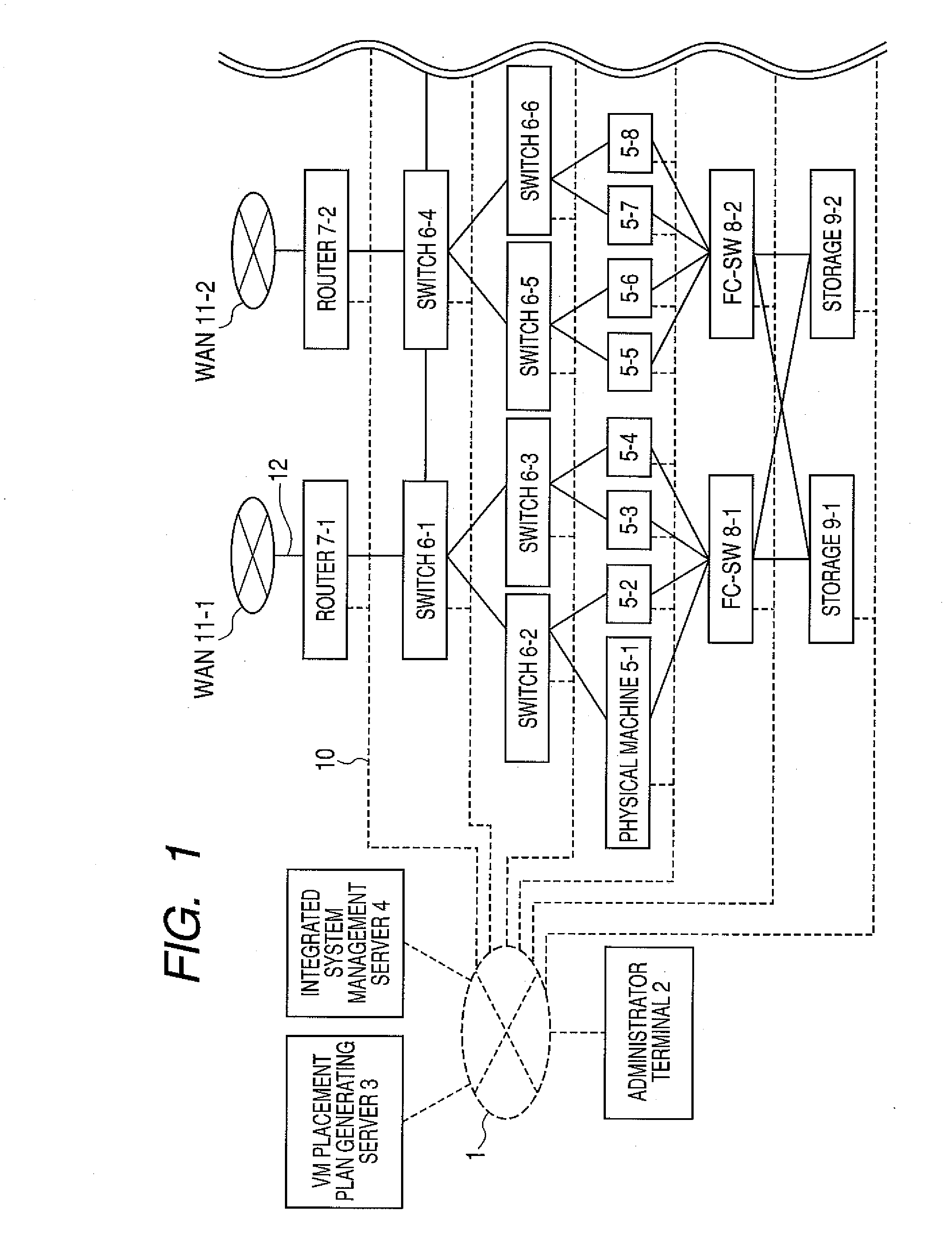
[0051]FIG. 1 schematically shows a data center system that is assumed to be a system in which the first and subsequent embodiments are implemented. This virtualized system is composed of an administrator terminal 2 which is an administrative client, a VM placement plan generating server 3, an integrated system management server 4, a plurality of physical machines 5, a plurality of switches 6, a plurality of routers 7, a plurality of fiber channel switches 8 (hereinafter abbreviated to FC-SWs), and storages 9.

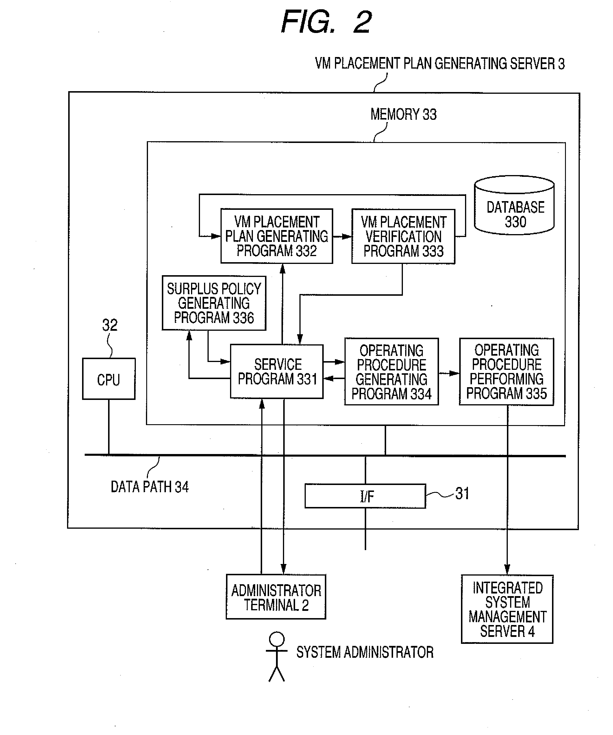
[0052]The administrator terminal 2, the VM placement plan generating server 3, and the integrated system management server 4 are commonly-used computer systems having a Central Processing Unit (CPU), a memory as a storage part, an interface (I / F) part, an input / output part, and other elements. Although they are shown with separate computer systems, a set of them may be comprised of a fewer number of computer systems by, e.g., implementing the VM placement plan generating server ...

second embodiment

[0173]In the foregoing first embodiment, one example of the VM placement plan generating server was discussed, wherein the server generates placement plans, based on one or more surplus policies. In the second embodiment, another example of the VM placement plan generating server is discussed, wherein the server generates placement plans, while adjusting a surplus policy repeatedly, based on results of validation of placement plans.

[0174]FIG. 21 is a functional block diagram showing an internal structure of a VM placement plan generating server 3-2 pertaining to the second embodiment. Difference from the first embodiment lies in that the memory 33-2 stores a surplus policy adjusting program 337. Along with the addition of the surplus policy adjusting program 337, some processes are added to the placement plan verification program 333-2, as will be described below. Others are the same as in the first embodiment. So, their explanation is skipped in this second embodiment section.

[0175...


PUM


Abstract

In a system having physical machine resources and network component resources, a resource management technique is provided that is effective for deploying virtual machines utilizing these resources. A surplus policy regarding surplus resources is prepared as a parameter adjustable by the system administrator. A placement plan generating program at a VM placement plan generating server generates placement plans for virtual machines in response to alteration of the surplus policy. Then, a placement plan verification program at the VM placement plan generating server validates whether each of the created placement plans complies with the altered surplus policy. This validation is performed by simulating the amounts of utilization of both physical machine resources and network component resources. The VM placement plan generating server presents the placement plans that passed this validation, as those causing no problem in performance, to the system administrator through the use of an administrator terminal.

Description

CLAIM OF PRIORITY[0001]The present application claims priority from Japanese patent application JP 2008-324848 filed on Dec. 22, 2008, the content of which is hereby incorporated by reference into this application.FIELD OF THE INVENTION[0002]The present invention relates to management of resources of a system composed of various types of equipment units, particularly, to a resource management technique for deploying virtual machines in a system having virtualized server resources, network resources, and the like.BACKGROUND OF THE INVENTION[0003]Due to the development of virtual techniques during late years, data center operators have begun to provide a service of generating a virtual machine environment on demand.[0004]In such a service, virtual machines having significantly different amounts of resources required would coexist in one data center. For example, virtual machines making much use of a Central Processing Unit (CPU) as resources, but making little use of a network bandwid...

Claims


Application Information

Patent Timeline
Patent Type & Authority Applications(United States)
IPC IPC(8): G06F15/173
CPCG06F9/5077
Inventor YOSHIZAWA, MASAHIROOKITA, HIDEKI
Owner HITACHI LTD
Why Eureka
Try Eureka