Light emitting device

a light-emitting device and light-emitting technology, which is applied in the direction of semiconductor devices for light sources, incadescent envelopes/vessels, light-emitting devices, etc., can solve the problems of lack of versatility, above-described special concave mirrors, and lack of versatility, so as to improve the uniformity ratio of illumination, brighten the irradiation surface, and use light more efficiently

Inactive Publication Date: 2010-07-01
PHOENIX ELECTRIC CO
View PDF5 Cites 13 Cited by
  • Summary
  • Abstract
  • Description
  • Claims
  • Application Information

AI Technical Summary

Benefits of technology

[0010]A main subject of the present invention is to provide a light emitting device which uses an ordinary concave mirror having a paraboloid or an ellipsoid and having one focal point, and reflects light emitted from a plurality of main light sources on the concave mirror so as to convert the reflected light to parallel light having brightness depending on the number of the main light sources in the case where the light reflection surface has the paraboloid, and so as to convert the reflected light to converging light, on the light converging point, having brightness depending on the number of the main light sources in the case where the light reflection surface has the ellipsoid. Another object of the present invention is to provide a light emitting device capable of reducing unnecessary light (=stray light), and to maximize the efficiency of the light emitted from a plurality of main light sources.
[0016]Moreover, when LEDs are used as the main light sources 26, a color temperature of light emitted therefrom varies in a wide range depending on the individual LEDs. When the light reflection surface 20 has an ellipsoid, light emitted from a plurality of main light sources (=LEDs) 26 converges on the light converging point F2. Accordingly, variation in the color temperature of the light from the respective main light sources 26 is uniformized at the light converging point F2, and thus it is possible to provide a light emitting device 10 having less variation in the color temperature of emitted light depending on the individual differences. In the case of parallel light, the same effect as above described will be obtained depending on the degree of mixture of light on the irradiation surface.
[0019]As another example (FIG. 9) of the first aspect, the light emitting device 10 may be provided an auxiliary light source 50, which emits light toward an irradiation region formed by light reflected on the concave mirror 12. The auxiliary light source 50 is arranged between reflection regions R in the concave mirror 12. When the reflected light travels as parallel light, a slightly dark region DR, which is generated at the center of the parallel light depending on a degree of overlapping of the parallel light, can be lighted by using the auxiliary light source 50, and consequently it is possible to increase a uniformity ratio of illuminance on the irradiation surface. In the case where the reflected light travels as converging light, it is possible to supplementarily increase the brightness at a light converging point.
[0025]According to the present aspect, in addition to the invention according to the first aspect, with the correcting lens 46 arranged on the irradiation direction side from the main light sources 26, it is possible to direct light (=stray light) to a predetermined radiation point, the light being not transmitted through the main lenses 29, but traveling toward the irradiation direction while deviating from an irradiation region, and causing “glare” to those who are in the surrounding area. (For example, in the case where the light reflection surface 20 has a paraboloid, a correcting lens 46 is arranged to convert the stray light to parallel light, whereas in the case where the light reflection surface 20 has an ellipsoid, the correcting lens 46 is arranged to cause the stray light to converge on a light converging point F2 of the ellipsoid.) Accordingly, it is possible to use light from a plurality of main light sources 26 more efficiently, and also possible to improve a uniformity ratio of illuminance on the irradiation surface.
[0026]As another example (FIG. 6 (b)) of the second aspect, the main light source 26 according to the second aspect is modified, and has a feature that a main lens non-transmitted light reflection surface (not shown) is arranged for each of the main light sources 26 on a side toward the concave mirror 12, or a main lens non-transmitted light reflection film 31 is arranged for each of the main light sources 26 on a surface of the side toward the concave mirror 12. Accordingly, the light emitted toward the concave mirror 12 is reflected toward the irradiation direction or toward the light reflection surface 20, whereby the light is directed toward the irradiation region by the main lenses 29 or the correcting lens 46. It is possible to use the light more efficiently.
[0027]According to the present invention, as a main effect, it is possible to irradiate an irradiation surface brighter with the use of a plurality of main light sources in proportion to the number of the main light sources while using a conventionally used concave mirror having a focal point. As a subsidiary effect, it is possible to provide a light emitting device which has excellent use efficiency of light.

Problems solved by technology

However, the discharge lamp or the halogen lamp needs large electric power and has large heat discharge.
The light emitting device 1 has a problem of lack of versatility.
In addition, the above-described special concave mirror 4 has a problem of its manufacturability.
That is, in the case of manufacturing the concave mirror 4 with glass, a thickness of the concave mirror 4 needs to be biased in accordance with shapes of the plurality of divided curved surfaces 3, which leads to deterioration in a yield of the material, and which causes difficulty in improving the accuracy of the shape.
Moreover, even in the case of using aluminum, the above-described problems are caused, and it is substantially impossible to mold the concave mirror 4 by spinning.
Moreover, in the case of using resin, a die for molding the concave mirror 4 will be of a complicated shape, and consequently, a cost for manufacturing the die is increased, and in addition, it will be difficult to improve the accuracy of the shape.
In addition, as above described, the concave mirror 4 has a plurality of focal points, and thus a portion of light, which is emitted from an LED 2 disposed at one focal point, is reflected on a divided curved surface 3 on a side opposite to the divided curved surface 3 facing the focal point, and is consequently converted to certain parallel light or converging light, which limits improvement in efficient use of light.

Method used


Image

  • Light emitting device
  • Light emitting device
  • Light emitting device

Examples


first embodiment

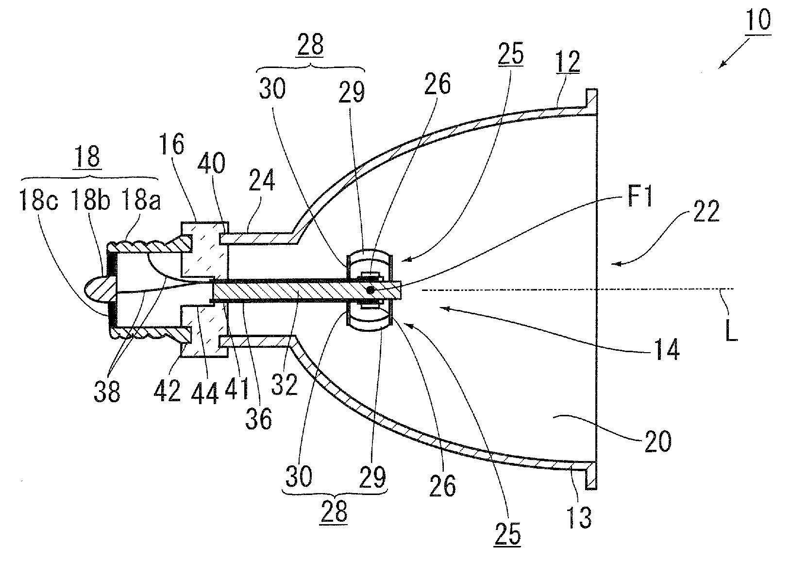
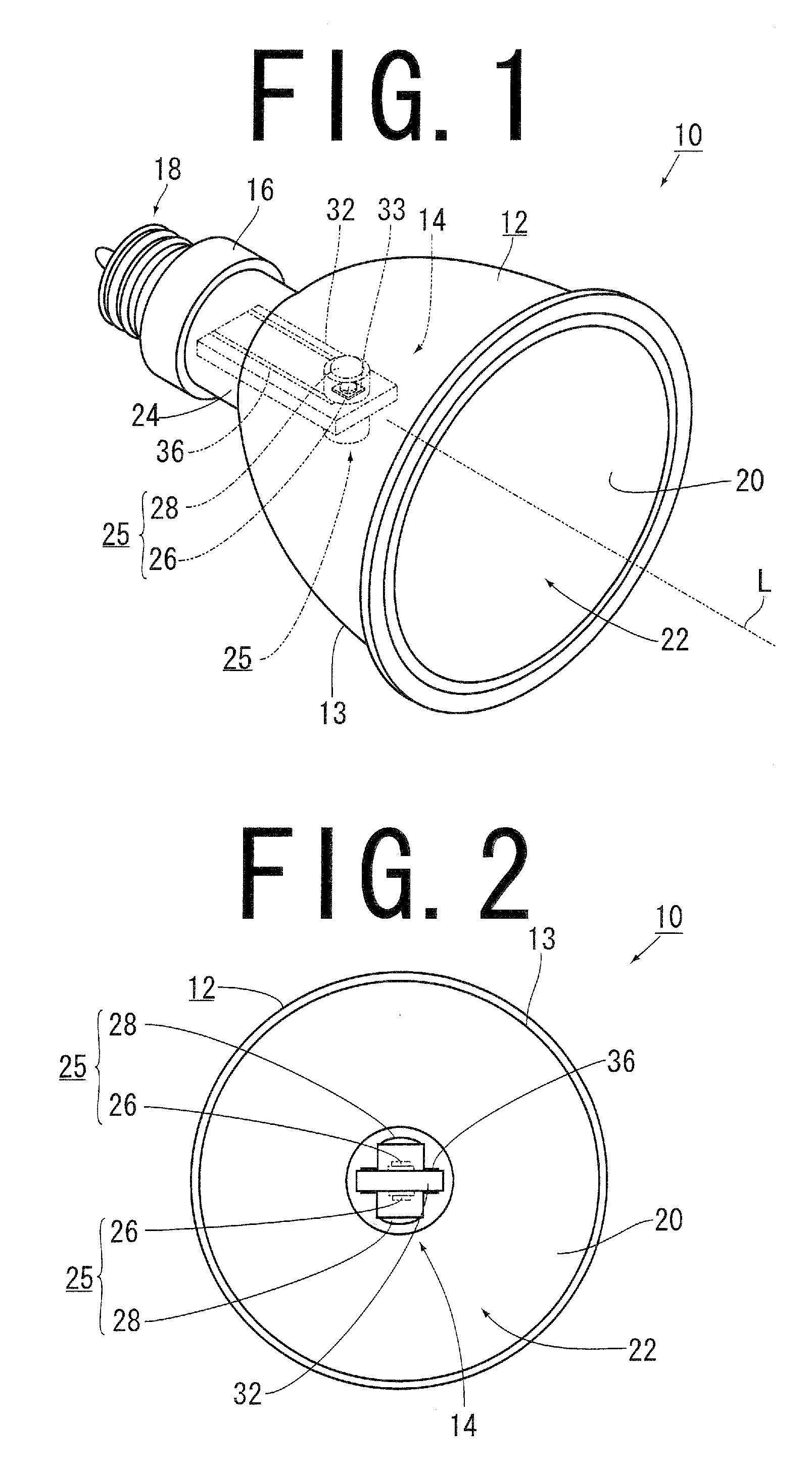
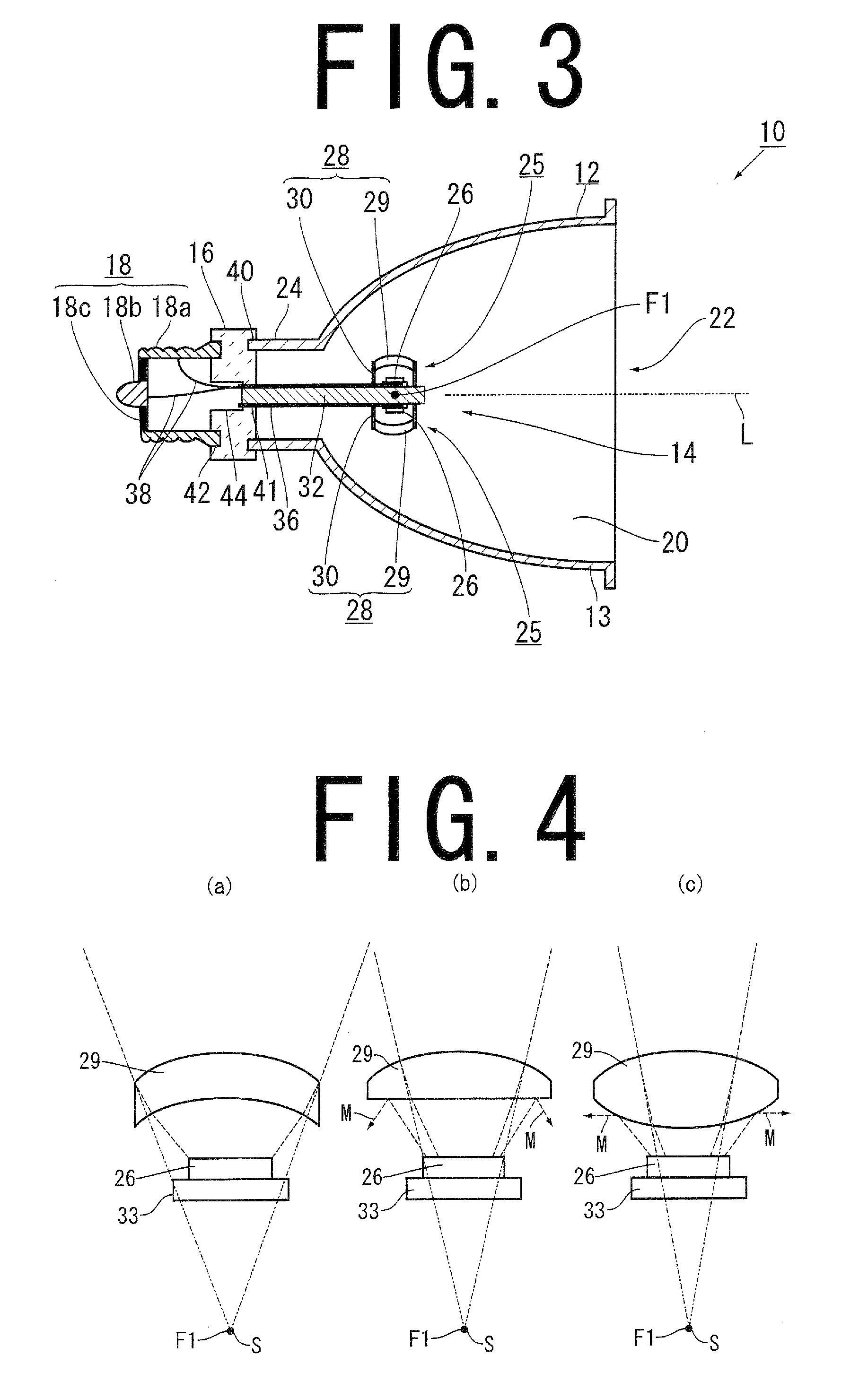
[0043]A light emitting device 10 according to the present invention is used for general illumination or for a projector, and comprises, as shown in FIG. 1 to FIG. 3, a concave mirror 12, a light source unit 14, a holder 16 for holding a light source unit 14, and a power supply terminal 18.

[0044]The concave mirror 12 has: a light reflection surface 20 which causes light internally emitted to be reflected; a light-emitting opening 22 through which light reflected on the light reflection surface 20 is outputted from the concave mirror 12; and a central fixing cylindrical portion 24 which is arranged at a central bottom portion of the concave mirror 12, and has a holder 16 fixed thereto. A straight line which passes through the center of the concave mirror 12, and is perpendicular to the light-emitting opening 22 is a central axis L of the concave mirror 12.

[0045]Glass, aluminum, and the like are used as a material of the concave mirror 12, and the light reflection surface 20 is treated...

second embodiment

[0062]In the same manner as the first embodiment, the light emitting device 10 according to the second embodiment also includes the concave mirror 12, the light source unit 14, the holder 16 for holding the light source unit 14, and the power supply terminal 18. In the first embodiment, the light reflection surface 20 is constituted of an ellipsoid, whereas, in the second embodiment, the light reflection surface 20 is constituted of a paraboloid. The constitution of the light reflection surface 20 is the only different point between the embodiments, and the first embodiment is incorporated for those common component parts in the present embodiment. Accordingly, the different light reflection surface 20 is mainly described with reference to FIGS. 1 to 3.

[0063]The light reflection surface 20 of the light emitting device 10 according to the second embodiment has a paraboloid centered on the central axis L. The “paraboloid” has a feature that causes all the light emitted from the focal ...


PUM


Abstract

A light emitting device comprises: a concave mirror having one focal point; a plurality of main light sources each of which is arranged between the focal point and a light reflection surface of the concave mirror, and emits light toward the light reflection surface; and a plurality of main lenses each of which is arranged between a corresponding one of the main light sources and the light reflection surface, refracts the light emitted from the corresponding main light source toward the light reflection surface, and produces a virtual image of the main light source on the focal point situated at a backside of the main light source.

Description

BACKGROUND OF THE INVENTION[0001]1. Field of the Invention[0002]The present invention relates to a light emitting device using a light emitting diode or the like as a main light source, being intended for general illumination and a projector, or the like.[0003]2. Description of the Background Art[0004]As a light emitting device used for general illumination and a projector, a combination of a concave mirror and a discharge lamp or a halogen lamp, in which a focal point of the concave mirror is positioned at a light emitting point of the lamp, is widely used. However, the discharge lamp or the halogen lamp needs large electric power and has large heat discharge. Thus, a light emitting diode (LED, representing a light source that has a lesser amount of light and a lesser amount of heat discharge than the discharge lamp) has been proposed to be used as a light source of the light emitting device. In the light emitting device, in order to compensate for the disadvantage of the LED that ...

Claims


Application Information

Patent Timeline
Patent Type & Authority Applications(United States)
IPC IPC(8): H01K1/30
CPCF21V5/04F21V13/04F21K9/233F21V5/046F21V7/06F21V7/08F21Y2115/10F21Y2107/90
Inventor KAZMIERSKI, ANDREI
Owner PHOENIX ELECTRIC CO
Why Eureka
Try Eureka