
Control circuit for light-emitting element

a control circuit and light-emitting element technology, applied in the field of control techniques, can solve the problems of deviating or being interrupted the frequency of the clock signal supplied by the microcomputer, and the control circuit of the light-emitting device can achieve the effect of preventing flickering on the screen

Inactive Publication Date: 2010-07-01
ROHM CO LTD
View PDF1 Cites 12 Cited by
  • Summary
  • Abstract
  • Description
  • Claims
  • Application Information

AI Technical Summary

Benefits of technology

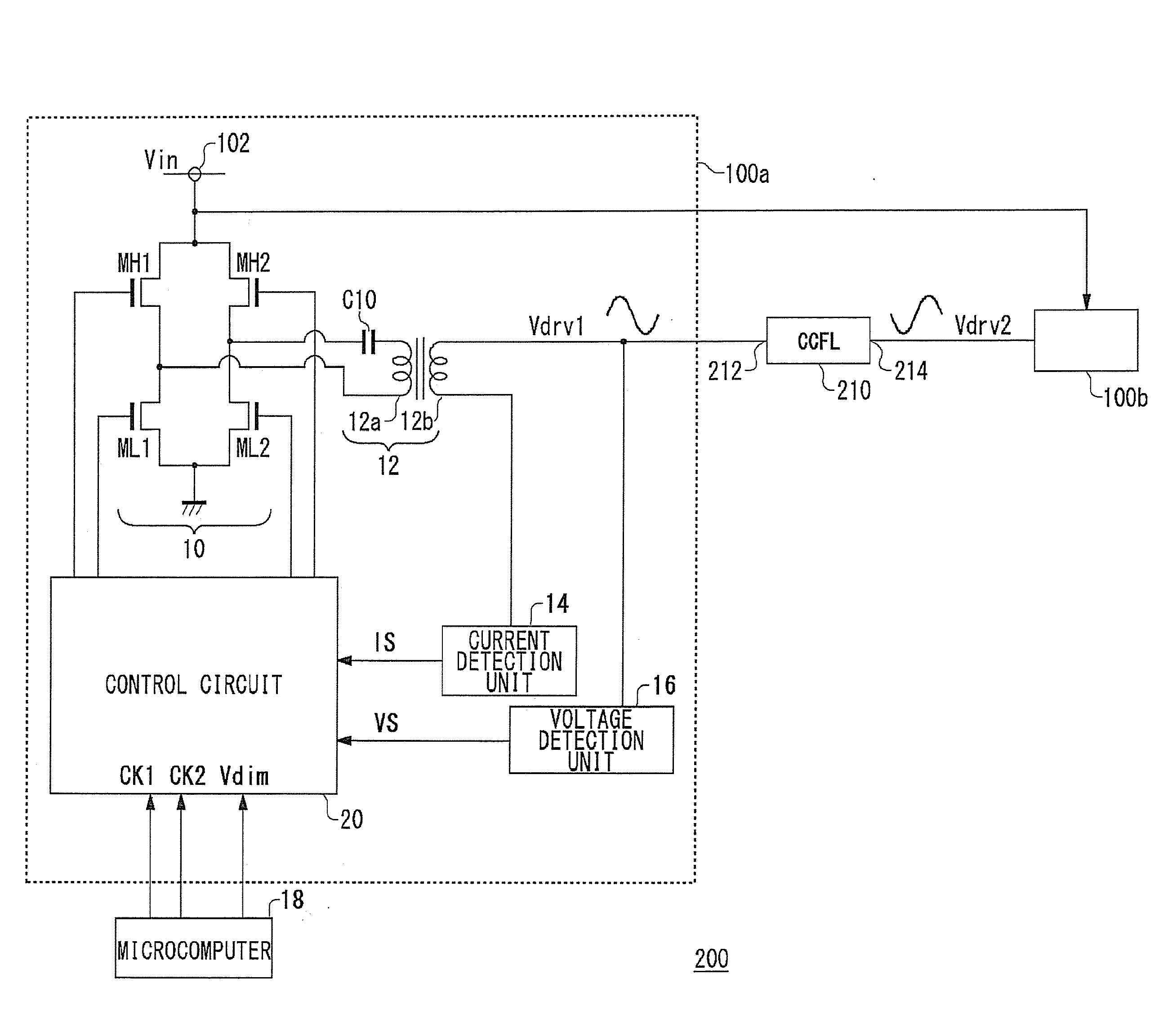
[0011]The present invention has been made in order to solve such a problem. Accordingly, it is an exemplary purpose of the present invention to provide a technique for driving a light-emitting element with high stability even in a case in which a synchronization clock signal supplied from an external circuit fluctuates.
[0013]Examples of the“cyclic signals” include cyclic triangle wave signals, sawtooth wave signals, and sine wave signals, in addition to cyclic pulse signals (rectangular wave signals). Also, examples of “light-emitting elements” include fluorescent lamps such as CCFLs, EEFLs, etc., and a wide range of devices driven according to a cyclic signal, such as organic EL (Electro-Luminance) elements, LEDs, etc. With such an arrangement, a driving signal can be generated based upon a signal generated by the internal oscillator. Thus, even in a case in which the frequency of the synchronization clock signal fluctuates or the synchronization clock signal is interrupted, such an arrangement is capable of providing highly stable driving of a light-emitting element.

Problems solved by technology

In some cases, the frequency of a clock signal supplied from a microcomputer can greatly deviate or can be interrupted due to a malfunction of the microcomputer.
In such a case, in a case in which the control circuit drives the inverter according to the clock signal, the luminance of the fluorescent lamp cannot be stably supplied, leading to flickering on a screen.
A similar problem can occur in control circuits for light-emitting devices other than a fluorescent lamp, examples of which include a control circuit for an LED driver for driving an LED.

Method used


Image

  • Control circuit for light-emitting element
  • Control circuit for light-emitting element
  • Control circuit for light-emitting element

Examples


Embodiment Construction

[0030]The invention will now be described based on preferred embodiments which do not intend to limit the scope of the present invention but exemplify the invention. All of the features and the combinations thereof described in the embodiment are not necessarily essential to the invention.

[0031]In the present specification, the state represented by the phrase “the member A is connected to the member B” includes a state in which the member A is indirectly connected to the member B via another member that does not affect the electric connection therebetween, in addition to a state in which the member A is physically and directly connected to the member B.

[0032]In the same way, the state represented by the phrase “the member C is provided between the member A and the member B” includes a state in which the member A is indirectly connected to the member C, or the member B is indirectly connected to the member C via another member that does not affect the electric connection therebetween...


PUM


Abstract

A control circuit generates a driving signal for driving a light-emitting element. An external synchronization oscillator receives a synchronization clock signal from an external circuit, and generates an external synchronization cyclic signal synchronously with the clock signal. An internal oscillator generates an internal cyclic signal having a predetermined frequency asynchronously with the synchronization clock signal. When the frequency of the external synchronization cyclic signal is within a predetermined range, the driving signal generating unit generates the driving signal based upon the external synchronization cyclic signal. When the frequency of the external synchronization cyclic signal deviates from the predetermined range, the driving signal generating unit generates the driving signal based upon the internal cyclic signal.

Description

BACKGROUND OF THE INVENTION[0001]1. Field of the Invention[0002]The present invention relates to a control technique for controlling a driving operation for a fluorescent lamp or an LED (light-emitting diode).[0003]2. Description of the Related Art[0004]In recent years, liquid crystal displays, which provide a display having a thin shape and a large size, have been becoming popular as replacements for CRT-based TVs. Liquid crystal displays include multiple cold cathode fluorescent lamps (which will be referred to as “CCFLs” hereafter) or external electrode fluorescent lamps (which will be referred to as “EEFLs” hereafter) arranged on the back face of a liquid crystal panel on which video images are to be displayed, which are used as light-emitting backlights. Alternatively, LEDs are coming to be used as replacements for the fluorescent lamps.[0005]The CCFL or EEFL is driven using an inverter (DC / AC converter) which boosts DC voltage of around 12 V, and which outputs the voltage thus...

Claims


Application Information

Patent Timeline
IPC IPC(8): G09G3/36H05B41/16
CPCG09G3/3406H05B41/2828
Inventor KIKUCHI, HIROKI
Owner ROHM CO LTD
Learn More