Imaging apparatus and imaging method

a technology of imaging apparatus and image, applied in the direction of instruments, television systems, exposure control, etc., can solve the problem of loss of simultaneousity between images obtained by subject illumination imaging and non-illuminating imaging

Inactive Publication Date: 2010-07-01
FUJIFILM CORP
View PDF1 Cites 7 Cited by
  • Summary
  • Abstract
  • Description
  • Claims
  • Application Information

AI Technical Summary

Benefits of technology

[0023]According to the presently disclosed subject matter, the signal charges accumulated in the imaging device are read out in a separated fashion with respect to the first groups and the second groups, and transfer of the signal charges is not performed between the subject-illuminating imaging and the subject-non-illuminating imaging. Therefore, a time interval of execution timing between the subject-illuminating imaging and the subject-non-illuminating imaging can be reduced, and the simultaneity between the subject-illuminating imaging and the subject-non-illuminating imaging may be improved.

Problems solved by technology

Therefore, simultaneity between images obtained by the subject-illuminating imaging and the subject-non-illuminating imaging may be lost.

Method used


Image

  • Imaging apparatus and imaging method
  • Imaging apparatus and imaging method
  • Imaging apparatus and imaging method

Examples


first embodiment

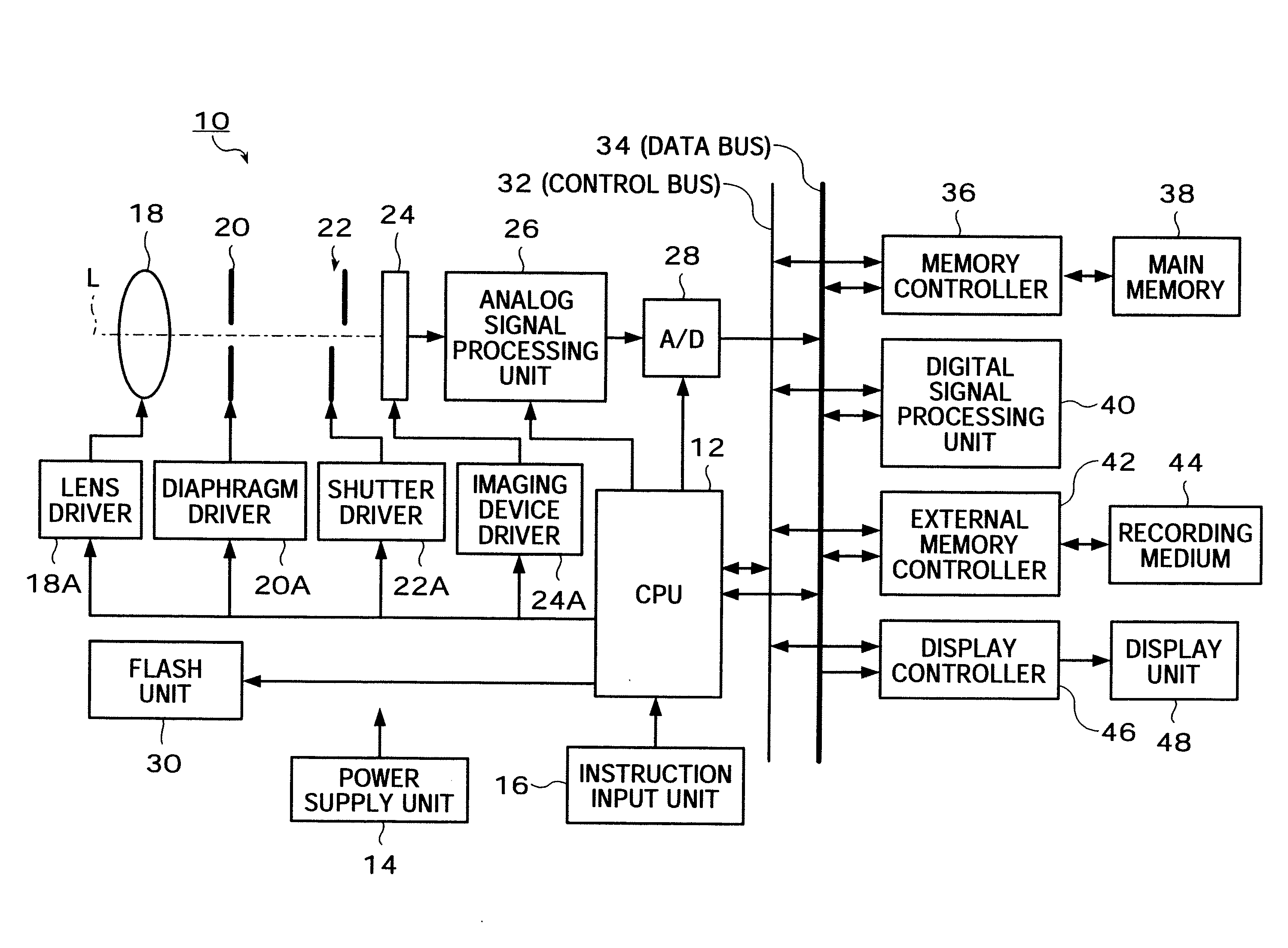
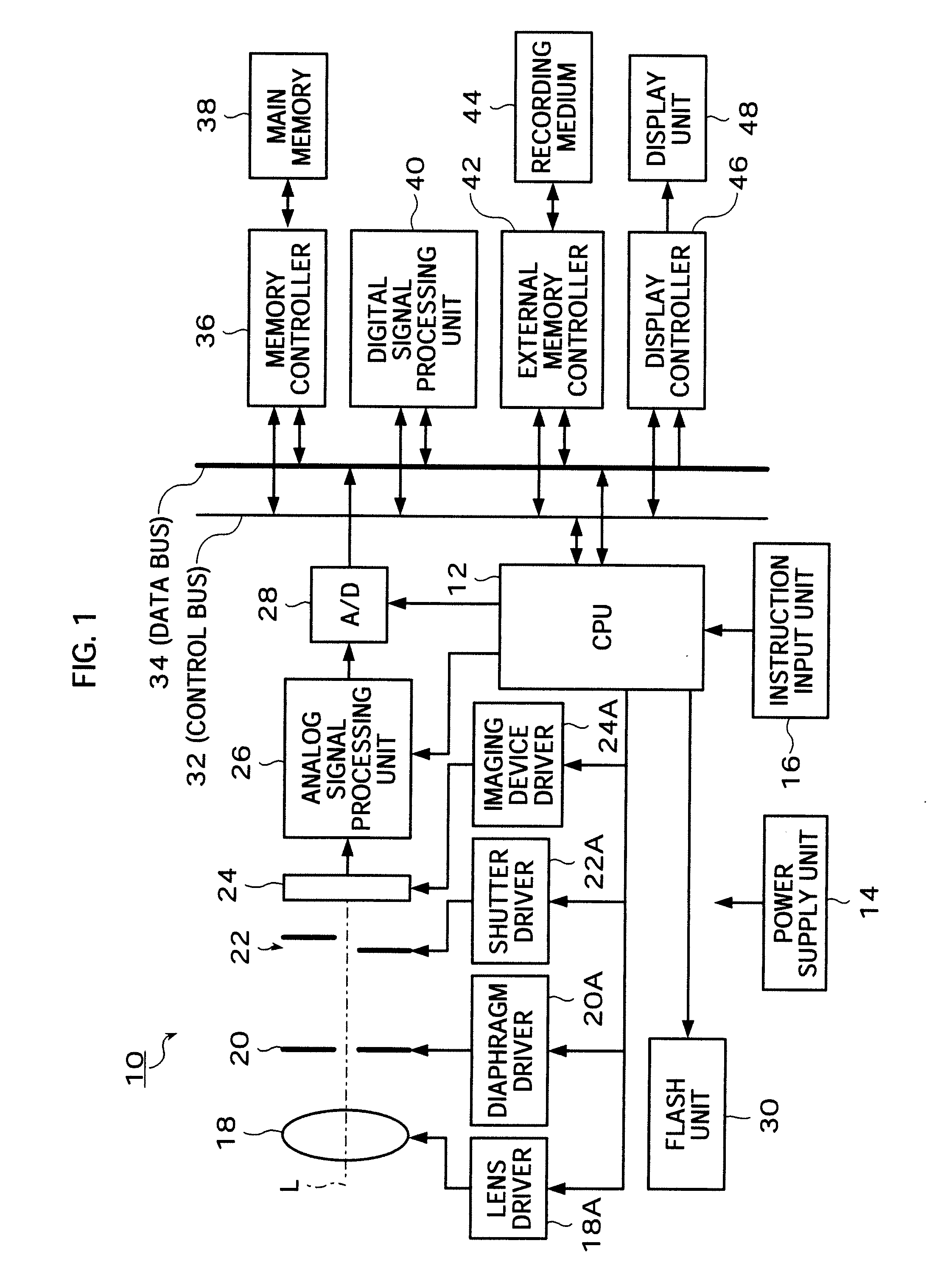
[0030]FIG. 1 is a block diagram showing an electronic camera of a first embodiment of the presently disclosed subject matter.

[0031]The electronic camera 10 of this embodiment includes a function of imaging and a function of reproducing and displaying a still image and a moving image.

[0032]A CPU (Central Processing Unit) 12 outputs an instruction to components of the electronic camera 10 via a control bus 32, and controls operation of the electronic camera 10.

[0033]The control bus 32 is a transmission line through which the instruction from the CPU 12 is transmitted to the components of the electronic camera 10. A data bus 34 is a transmission line through which various pieces of data such as an image signal are transmitted.

[0034]A power supply unit 14 includes a battery and a power supply circuit which converts electric power supplied by the battery into a prescribed voltage current, and supplies the current to the components of the electronic camera 10.

[0035]An instruction input un...

second embodiment

[0068]Next, a second embodiment of the presently disclosed subject matter will be described. It should be noted that the description on the same configuration as that of the above-mentioned first embodiment will be omitted.

[0069]FIG. 4 is a timing chart showing the second embodiment of a method for driving the imaging device in the consecutive imaging mode.

[0070]First of all, before exposure, OFD pulses are applied by the imaging device driver 24A to the imaging device 24, and charges accumulated in the pixels are drained to a side of the substrate on which the imaging device 24 is disposed, as shown in FIG. 4. Responsive to a half-press of the release button (S1-on), the above-mentioned imaging preparation process is executed, and the exposure time periods of the subject-illuminating imaging and the subject-non-illuminating imaging are determined.

[0071]Next, responsive to a full-press of the release button (S2-on), the application of the OFD pulses is terminated, and a flash pulse ...


PUM


Abstract

An imaging method for taking an image using an imaging apparatus including an imaging device which includes first rows of pixels including first groups of light receiving elements and second rows of pixels including second groups of light receiving elements; first charge transfer lines; and second charge transfer lines, includes steps of: consecutively performing a subject-illuminating imaging and a subject-non-illuminating imaging, responsive to an input of an imaging instruction; reading out the charges accumulated in the first groups and the second groups of light receiving elements, and transferring the charges via the first and second charge transfer lines, respectively, after the subject-illuminating imaging and the subject-non-illuminating imaging; and acquiring an image by the subject-illuminating imaging and an image by the subject-non-illuminating imaging from the charges having been read out and transferred from the first groups and the second groups of light receiving elements, respectively.

Description

[0001]This application claims the priority benefit under 35 U.S.C. §119 of Japanese Patent Application No. 2008-330974 filed on Dec. 25, 2008 and Japanese Patent Application No. 2009-243684 filed on Oct. 22, 2009, which is hereby incorporated in its entirety by reference.BACKGROUND OF THE INVENTION[0002]1. Field of the Invention[0003]The presently disclosed subject matter relates to an imaging apparatus and an imaging method, and more particularly, to an imaging apparatus including a flash unit and an imaging method using the imaging apparatus.[0004]2. Description of the Related Art[0005]Japanese Patent Application Laid-Open No. 2004-54231 discloses a camera performing at least each one time of non-flash imaging with no flash firing and flash imaging with flash firing responsive to one shutter release operation.[0006]Japanese Patent Application Laid-Open No. 2007-256907 discloses a digital camera including an imaging device which includes a special consecutive imaging mode of consec...

Claims


Application Information

Patent Timeline
Patent Type & Authority Applications(United States)
IPC IPC(8): H04N5/222G03B7/16G03B15/03G03B15/05H04N5/238H04N5/335H04N5/353H04N5/369H04N5/372H04N5/374H04N101/00
CPCH04N5/2354H04N5/35554H04N5/35572H04N5/35581H04N23/74H04N25/587H04N25/583H04N25/589
Inventor KAWAMURA, KAZUO
Owner FUJIFILM CORP
Why Eureka
Try Eureka