Optical systems

Inactive Publication Date: 2010-07-01
LIGHT BLUE OPTICS
View PDF8 Cites 95 Cited by
  • Summary
  • Abstract
  • Description
  • Claims
  • Application Information

AI Technical Summary

Benefits of technology

[0013]Embodiments of the above-described method also provide the advantage, in the context of a manufacturer providing head up displays for a range of different vehicles, of not requiring an optical hardware re-design for each separate shape of display surface (windshield).

Problems solved by technology

The techniques we describe have advantages for vehicle head up displays but there are practical problems in their use, in particular because the image is generally formed on a curved surface such as a windshield.

Method used


Image

  • Optical systems
  • Optical systems
  • Optical systems

Examples


Embodiment Construction

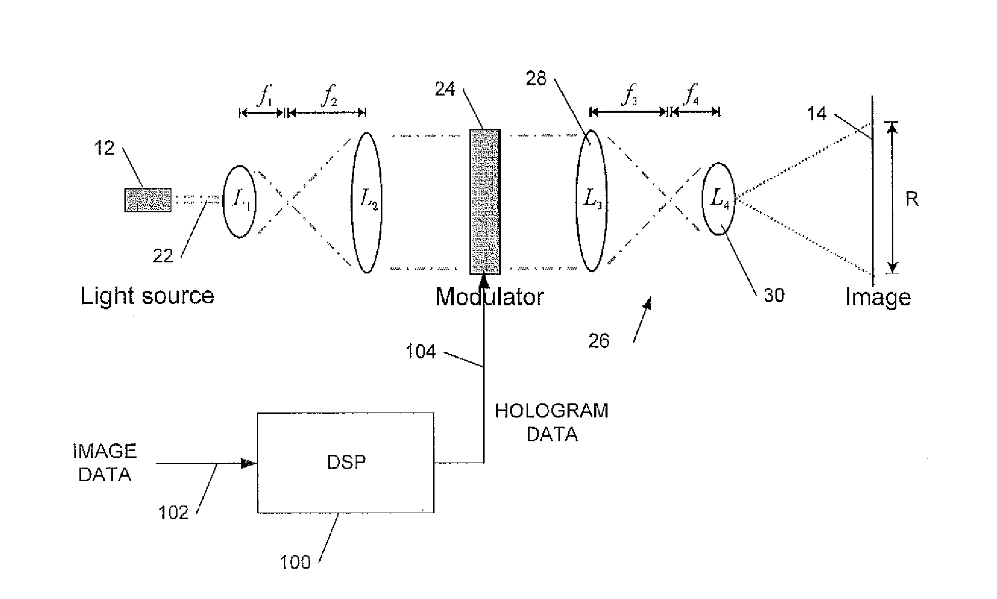
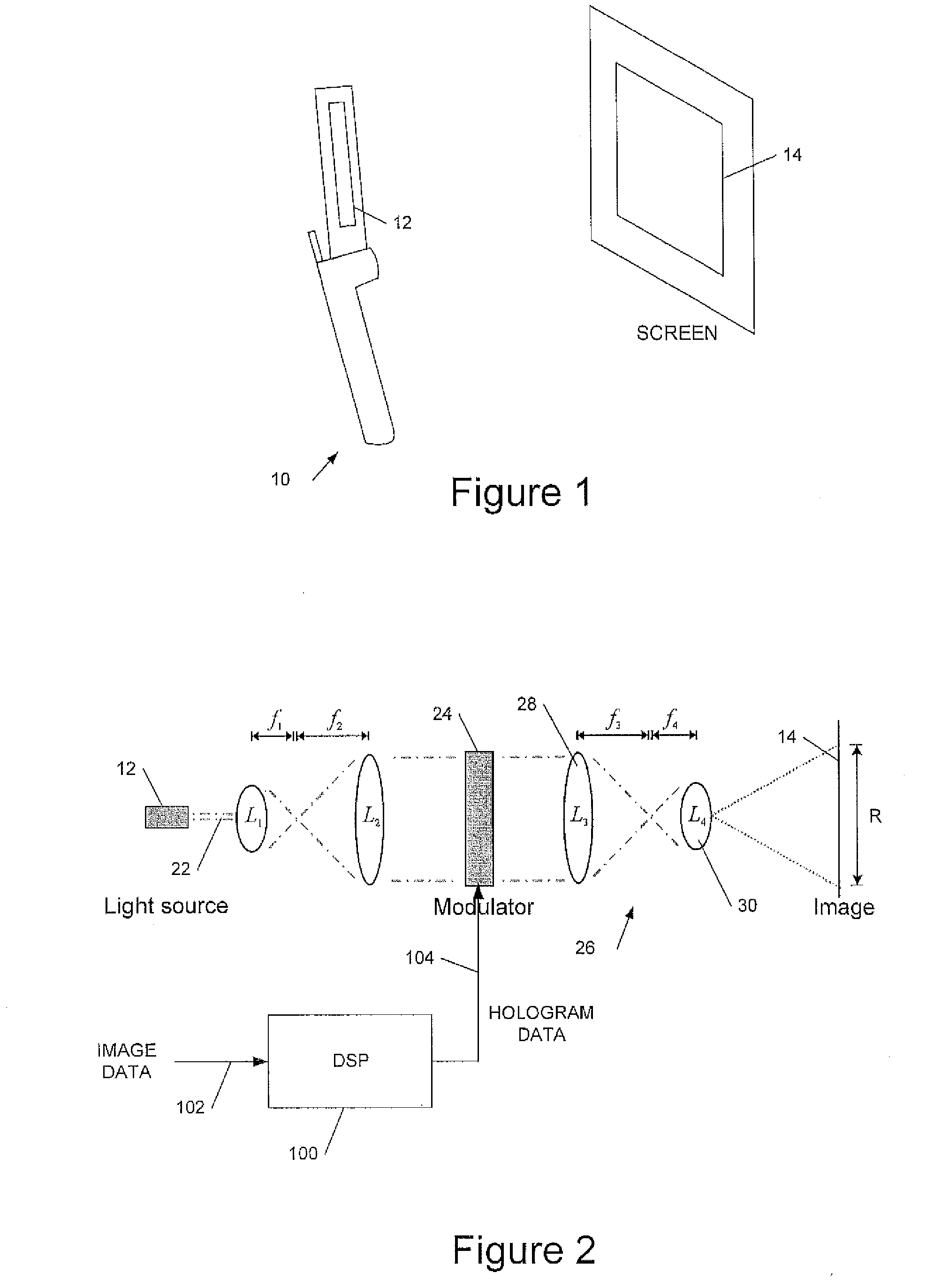
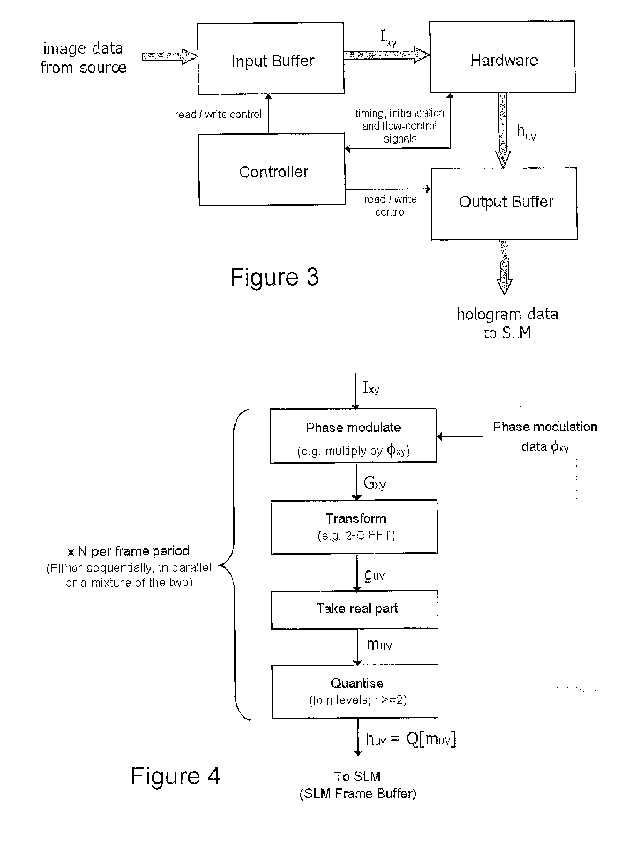
[0037]We have previously described, in UK patent application number 0512179.3 filed 15 Jun. 2005, incorporated by reference, a holographic projection module comprising a substantially monochromatic light source such as a laser diode; a spatial light modulator (SLM) to (phase) modulate the light to provide a hologram for generating a displayed image; and a demagnifying optical system to increase the divergence of the modulated light to form the displayed image. Absent the demagnifying optics the size (and distance from the SLM) of a displayed image depends on the pixel size of the SLM, smaller pixels diffracting the light more to produce a larger image. Typically an image would need to be viewed at a distance of several metres or more. The demagnifying optics increase the diffraction, thus allowing an image of a useful size to be displayed at a practical distance. Moreover the displayed image is substantially focus-free: that is the image is substantially in focus over a wide range o...


PUM


Abstract

A holographic head up display (HUD) for a vehicle to display an image holographically on a curved display surface such as a windshield is disclosed. The HUD can include a spatial light modulator (SLM) to display a hologram, an illumination system to illuminate said displayed hologram, projection optics to project light from said hologram onto said display surface to form said image, and a processor configured to process said image data to generate hologram data for display on the SLM to form said image. The HUD can further include a non-volatile data memory coupled to said processor to store wavefront correction data for said display surface, and the processor can be configured to apply a wavefront correction responsive to said stored wavefront correction data when generating the hologram data to correct the image for aberration due to a shape of said display surface.

Description

CROSS-REFERENCE TO RELATED APPLICATION[0001]This application is the U.S. National Phase under 35 U.S.C. §371 of International Application No. PCT / GB2008 / 050224, filed Mar. 28, 2008, designating United States and published in English on Oct. 9, 2008, as WO 2008 / 120015, which claims priority to United Kingdom Application No. 0706264.9, filed on Mar. 30, 2007 and U.S. Provisional Patent Application No. 60 / 909,394, filed on Mar. 30, 2007.FIELD OF THE INVENTION[0002]This invention relates to holographic head up displays (HUDs), in particular correcting for aberrations due to projection onto a curved display surface such as a windshield, and to related methods of displaying an image holographically and to corresponding processor control code.BACKGROUND TO THE INVENTION[0003]We have previously described techniques for displaying an image holographically (see, for example, WO 2005 / 059660, WO 2006 / 134398, GB2429355 and WO 2006 / 134404, all hereby incorporated by reference in their entirety). ...

Claims


Application Information

Patent Timeline
Patent Type & Authority Applications(United States)
IPC IPC(8): G03H1/08G03H1/22
CPCG02B26/06G02B27/0068G02B27/0103G02B27/46G02B27/48G02B2027/011G03H1/0808G03H1/2205G03H1/2294G03H2001/221G03H2001/2213G03H2001/2218G03H2001/2221G03H2001/2255G03H2225/32G03H2001/0825G03H2001/2284G03H2001/2297G02B27/01G03H1/08G03H1/22
Inventor BUCKLEY, EDWARDGIL-LEYVA, DIEGO
Owner LIGHT BLUE OPTICS
Why Eureka
Try Eureka