
Collection optic for solar concentrating wedge

Inactive Publication Date: 2010-07-01
MURTHA R MICHAEL
View PDF5 Cites 18 Cited by
  • Summary
  • Abstract
  • Description
  • Claims
  • Application Information

AI Technical Summary

Benefits of technology

[0006]Another object is to greatly reduce the cosine losses associated with the low profile wedge. Other objects and advantages will become apparent from the following detailed description and accompanying drawings.

Problems solved by technology

In the past, however, each potential advantage was cancelled by the fact that a low profile wedge could only collect light from low in the sky.

Method used


Image

  • Collection optic for solar concentrating wedge
  • Collection optic for solar concentrating wedge
  • Collection optic for solar concentrating wedge

Examples


Embodiment Construction

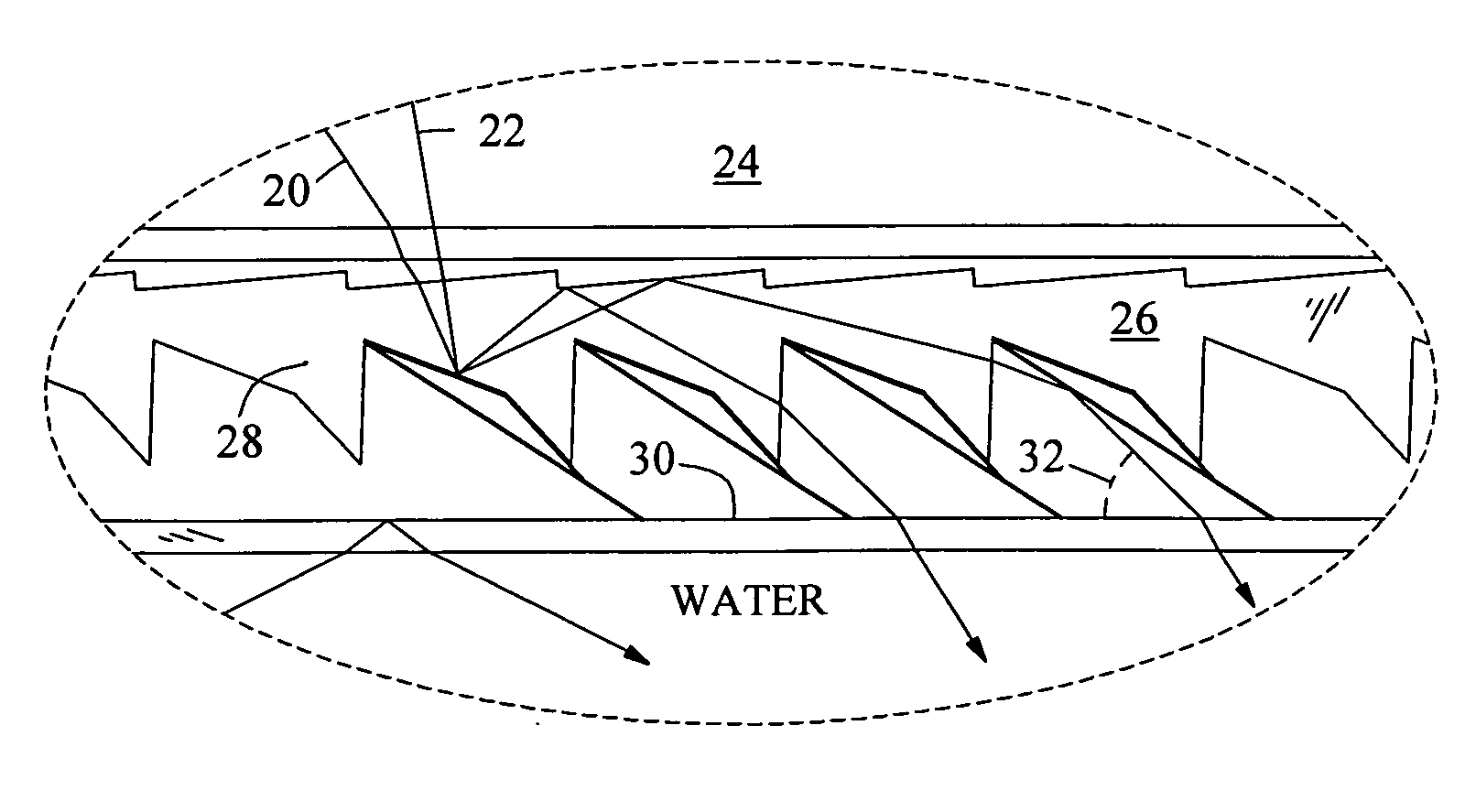
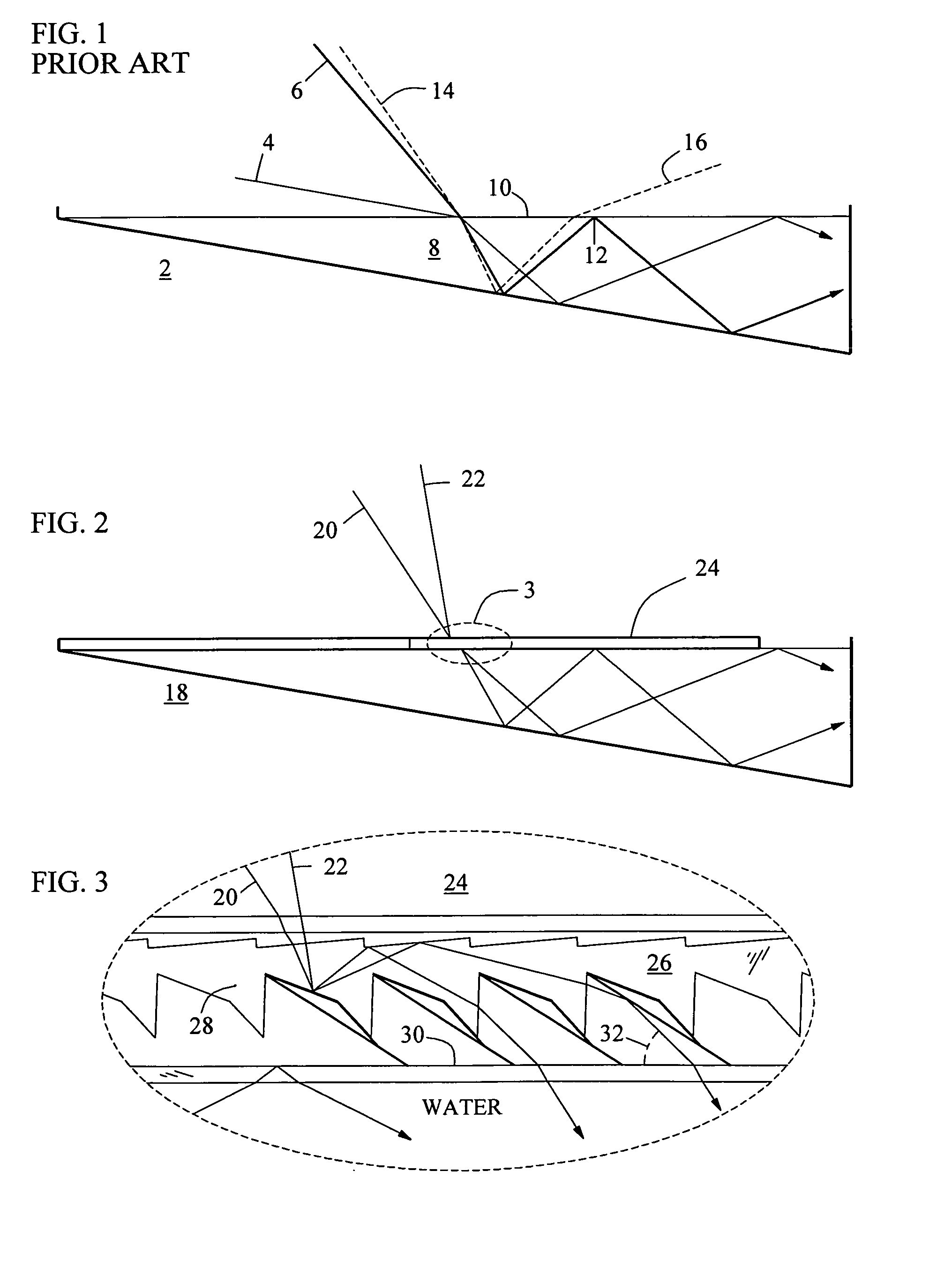
[0017]In FIG. 1, a prior art water-filled wedge 2 is shown collecting sunlight. Rays 4 and 6 outline the angular field of view of the nontracking solar concentrator. Ray 6 is the maximum elevation ray that the wedge can collect. After entering water 8 and reflecting from the bottom, ray 6 approaches water surface 10 at greater than the critical angle and is totally internally reflected 12 back into the water toward the focus. Whereas, if high ray 14 enters the water, it will reflect and exit the water as lost energy 16. Only the light between rays 4 and6 can be collected.

[0018]A major problem for the prior art wedge is that before arriving at the collector the low-angled light passes through an extra thick air mass which absorbs much of the radiant energy.

[0019]The horizontal wedge also suffers a cosine loss. The light approaches water surface 10 at an oblique angle, causing a further decrease in the energy density of the light. For example, 60° incident light has an energy density ...


PUM


Abstract

A nontracking solar concentrator, called the wedge, is given the ability to collect overhead light. This is made possible by a new prism, having the cross section of a cornucopia, that delivers an abundance of bright light into the wedge to create a higher intensity focus.

Description

BACKGROUND OF THE INVENTION[0001]This invention relates to the collection of sunlight, specifically to a new panel that delivers overhead light into a solar concentrating wedge.[0002]The two most practical nontracking solar thermal concentrators are the well known compound parabolic concentrator (CPC) and the lesser known optical wedge. Both collectors use a reflective geometry, instead of sun-tracking machinery, to focus light onto a heat pipe.[0003]The low profile wedge is scalable. When filled with inexpensive water, the wedge can be built with a very large collection area and take advantage of the economies of scale that are necessary to become cost effective. The water-filled wedge can also transport any absorbed energy by flowing to the focus. In the past, however, each potential advantage was cancelled by the fact that a low profile wedge could only collect light from low in the sky.SUMMARY OF THE INVENTION[0004]The primary object of this invention is to allow the wedge to co...

Claims


Application Information

Patent Timeline
IPC IPC(8): G02B5/08
CPCG02B5/045Y02E10/40F24S23/10F24S2023/88F24S23/70
Inventor MURTHA, R. MICHAEL
Owner MURTHA R MICHAEL
Learn More