Self-sealing microreactor and method for carrying out a reaction

a microreactor and self-sealing technology, applied in the field of self-sealing microreactors and methods for carrying out reactions, to achieve the effect of preventing contamination

Active Publication Date: 2010-07-01
STMICROELECTRONICS SRL
View PDF23 Cites 10 Cited by
  • Summary
  • Abstract
  • Description
  • Claims
  • Application Information

AI Technical Summary

Benefits of technology

[0013]The present invention provides a microreactor for performing chemical or biochemical reactions and a method for performing those reactions, as claimed in claims 1 and 9, respectively. Generally speaking the self-sealing reactor of the invention employs a meltable portion to seal the chamber. The meltable portion also has cavities for receiving a sample for analysis. Thus, dur

Problems solved by technology

However, the melted material is immiscible with the sample, thus preventi

Method used


Image

  • Self-sealing microreactor and method for carrying out a reaction
  • Self-sealing microreactor and method for carrying out a reaction
  • Self-sealing microreactor and method for carrying out a reaction

Examples


Embodiment Construction

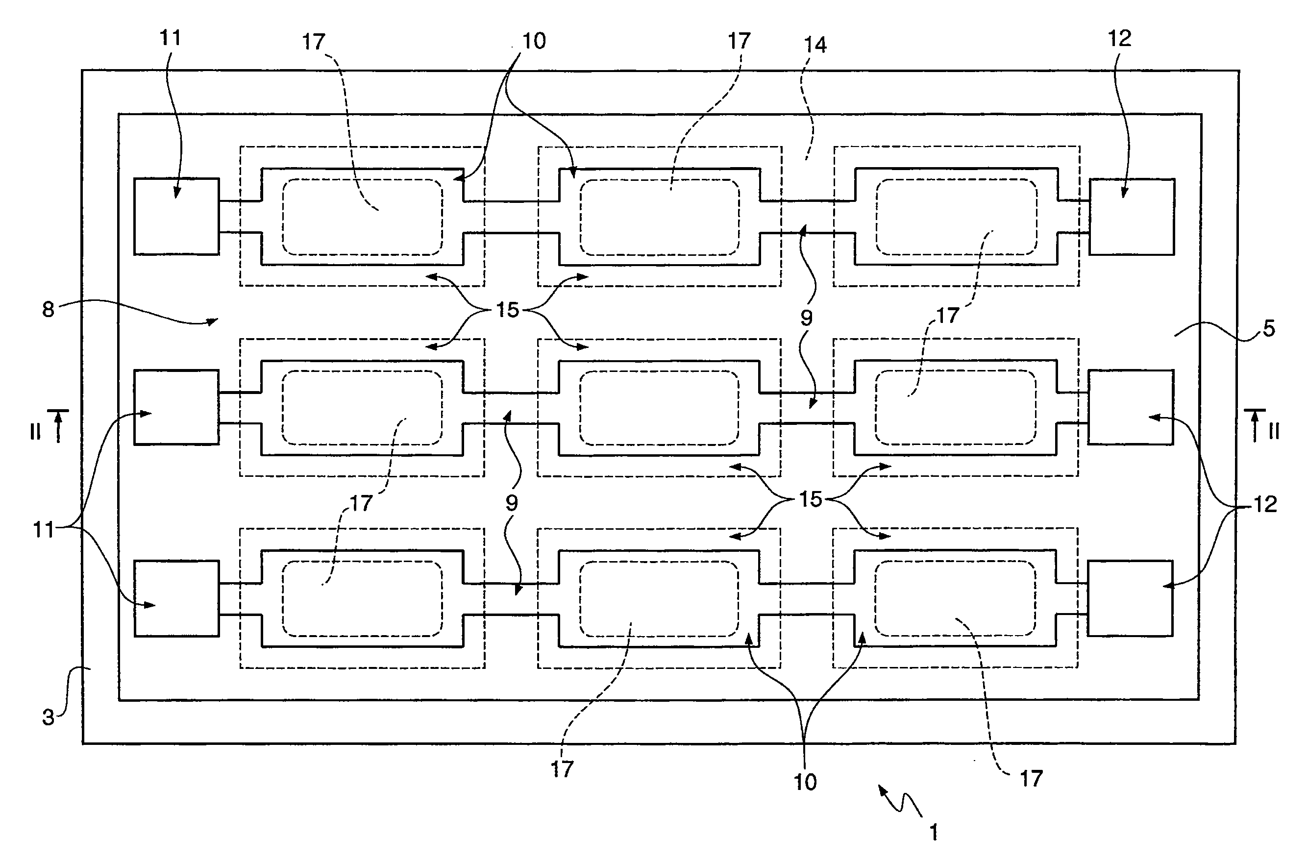
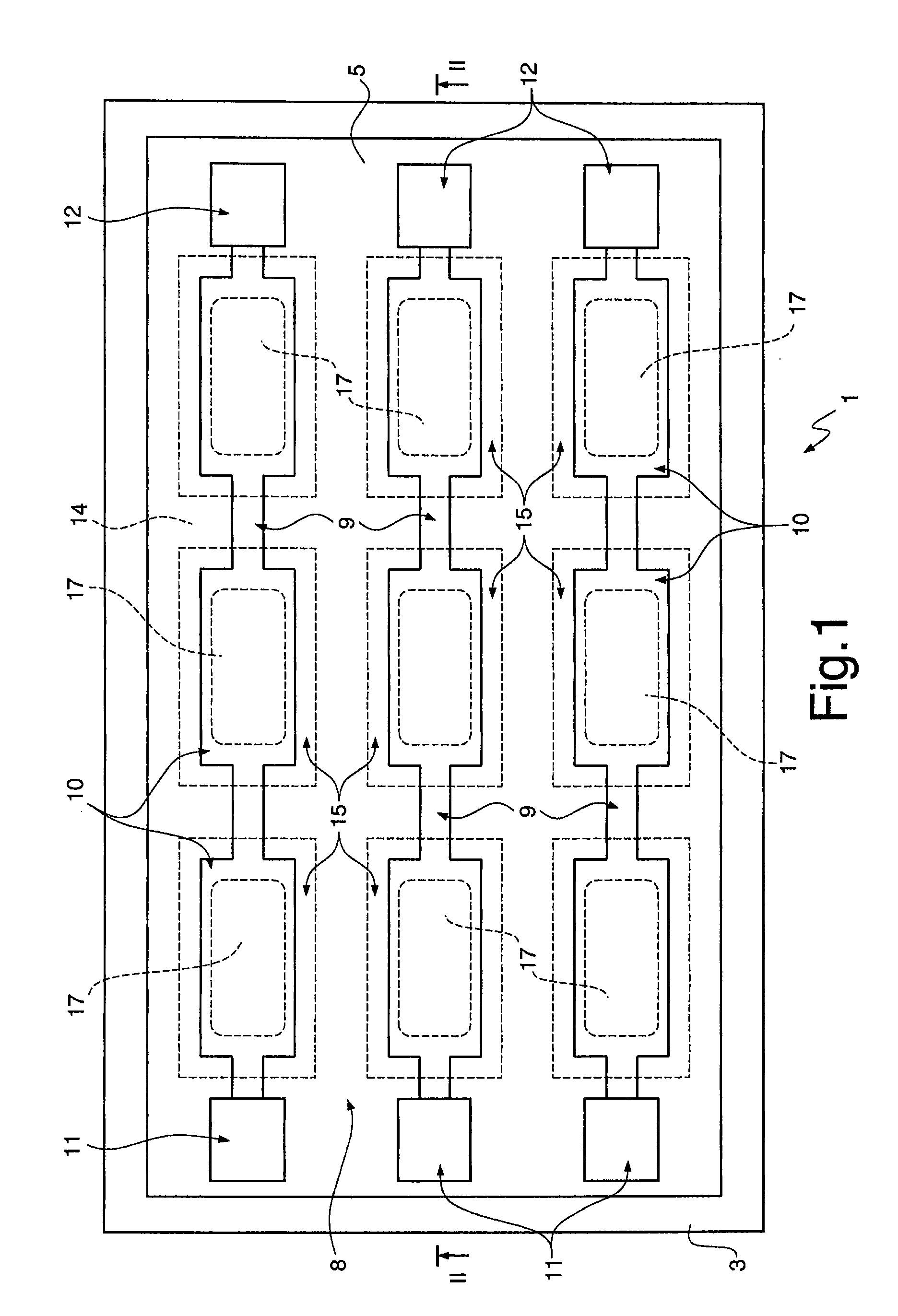
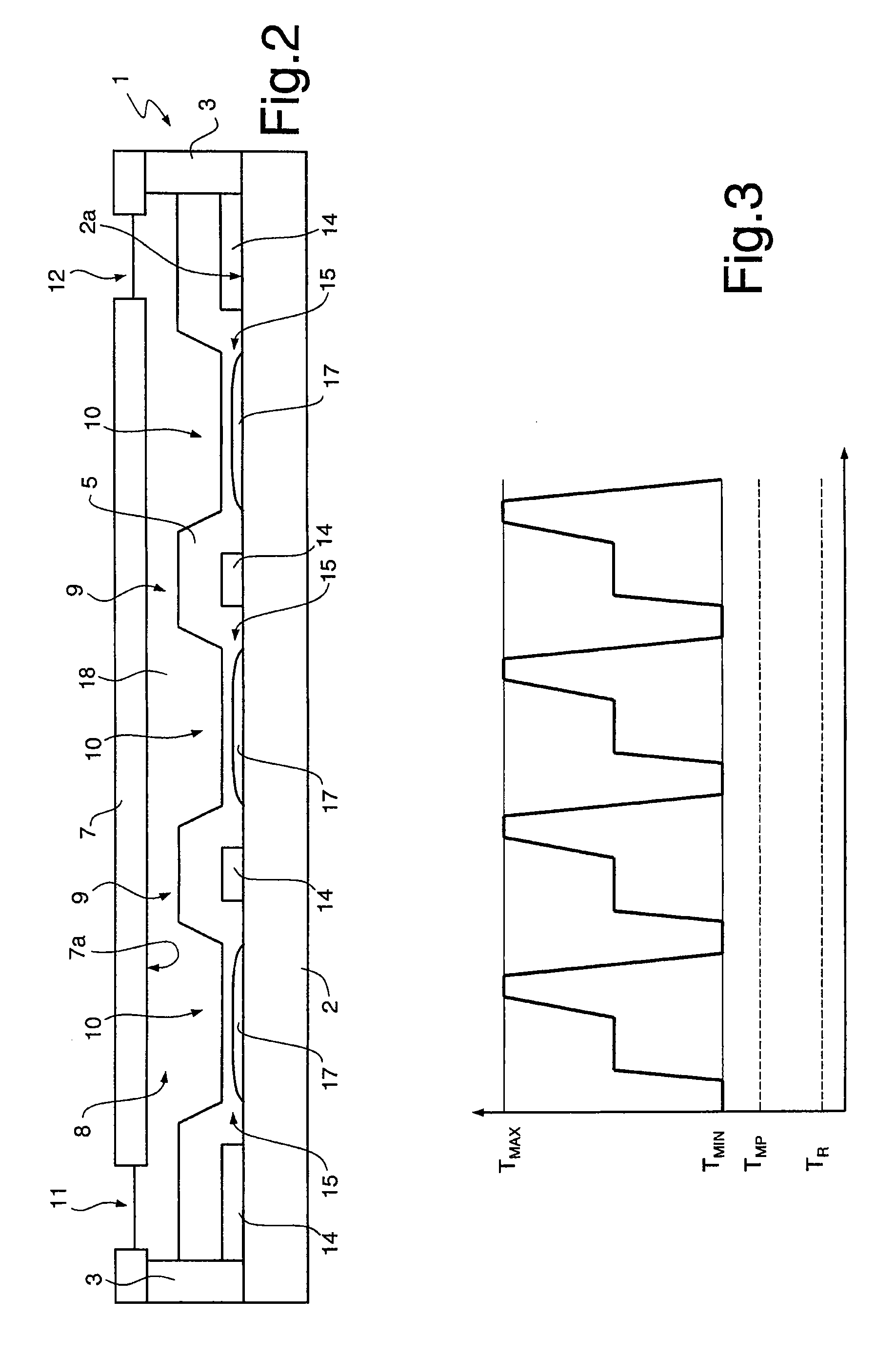
[0023]FIGS. 1 and 2 show a microreactor, namely for Lab-on-Chip applications, as a whole designated by the reference number 1. The microreactor 1 comprises a substrate 2 (seen in FIG. 2), a frame 3, a meltable layer 5 and a cap plate 7 (not shown in FIG. 1 for clarity).

[0024]The substrate 2 may be made of a variety of materials, such as a semiconductor material, glass, ceramic, or plastic or other resin. In one embodiment, for example, the substrate 2 is of monocrystalline silicon.

[0025]The frame 3 is bonded to the substrate 2 along an outer perimeter thereof, thus forming a shell structure having a bottom surface (the substrate 2) and a peripheral or side wall (the frame 3). Alternatively, the frame 3 may be integral with the substrate 2, for example by etching or by deposition of an edge as needed on the substrate.

[0026]The shell structure is closed by the cap plate 7, that is bonded, welded, glued or otherwise attached to the frame 3. In one embodiment, the frame 3 and the cap pl...


PUM


Abstract

A microreactor includes a shell structure (2, 3), having a bottom wall (2) and a peripheral wall (3); a layer (5), accommodated in the shell structure (2, 3) and having cavities (9, 10) formed therein, the cavities being accessible form outside the shell structure (2, 3); reagents (17), arranged between the bottom wall (2) and the layer (5), at locations corresponding to the cavities (9, 10). The layer (5) is made of a meltable material that is solid at room temperature, has a melting point (TMP) lower than a maximum operative temperature (TMAX) required by reactions performable through the microreactor (1) and is not miscible with water. The melting point (TMP) may be between 50° C. and 70° C. In one embodiment, the melting point (TMP) is lower than a minimum operative temperature (TMIN) required by reactions performable through the microreactor (1).

Description

CROSS-REFERENCE TO RELATED APPLICATIONS[0001]This application claims priority to Italian Application No. TO2008A001001 filed on Dec. 29, 2008, incorporated herein by reference in its entirety.FEDERALLY SPONSORED RESEARCH STATEMENT[0002]Not applicable.REFERENCE TO MICROFICHE APPENDIX[0003]Not applicable.FIELD OF THE INVENTION[0004]The present invention relates to a self-sealing microreactor and to a method for carrying out a reaction.BACKGROUND OF THE INVENTION[0005]Lab-On-Chip (LoC) systems are designed to carry out one or more steps of a chemical or biological process, often in a disposable sample cartridge or a silicon chip that is controlled and read by a reusable, portable device. For example, LoC systems are widely used to perform analyses such as PCR amplification, antibody testing, biochemical reactions, and microarray-based DNA, RNA, or protein analyses.[0006]Lab-On-Chip systems are proving to be effective in a wide range of practical situations and provide several advantage...

Claims


Application Information

Patent Timeline
IPC IPC(8): G01N1/00B81B7/00G01N33/50
CPCB01L3/50851B01L3/50853B01L3/5088B01L7/52B01L2200/0673B01L2200/0689B01L2200/141B01L2200/142B01L2200/148B01L2300/0819B01L2300/161B01L2300/1822B01L2300/1827B01L2300/1844Y10T436/25875Y10T436/143333Y10T436/25
Inventor BIANCHESSI, MARCO ANGELOCOCCI, ALESSANDRO
Owner STMICROELECTRONICS SRL
Why Eureka
Try Eureka