
Lock Assembly

Inactive Publication Date: 2010-07-08
GAINSBOROUGH HARDWARE INDS
View PDF3 Cites 2 Cited by
  • Summary
  • Abstract
  • Description
  • Claims
  • Application Information

AI Technical Summary

Benefits of technology

[0005]It is an object of the invention to substantially overcome or

Problems solved by technology

A disadvantage of this arrangement is that, if the powered barrel is damaged, for example by vandalism or by unauthorised attempts to open the door, then any authorised person subsequently attempting to open the door will be locked out.
Known lock arrangements of this type are also unsuitable for installation with the key driven barrel on the outside and the powered cylinder on the inside as, in the event of a power or other failure of the actuator, persons can be locked on the inward side of the door (i.e. inside the building).

Method used


Image

  • Lock Assembly
  • Lock Assembly
  • Lock Assembly

Examples


Embodiment Construction

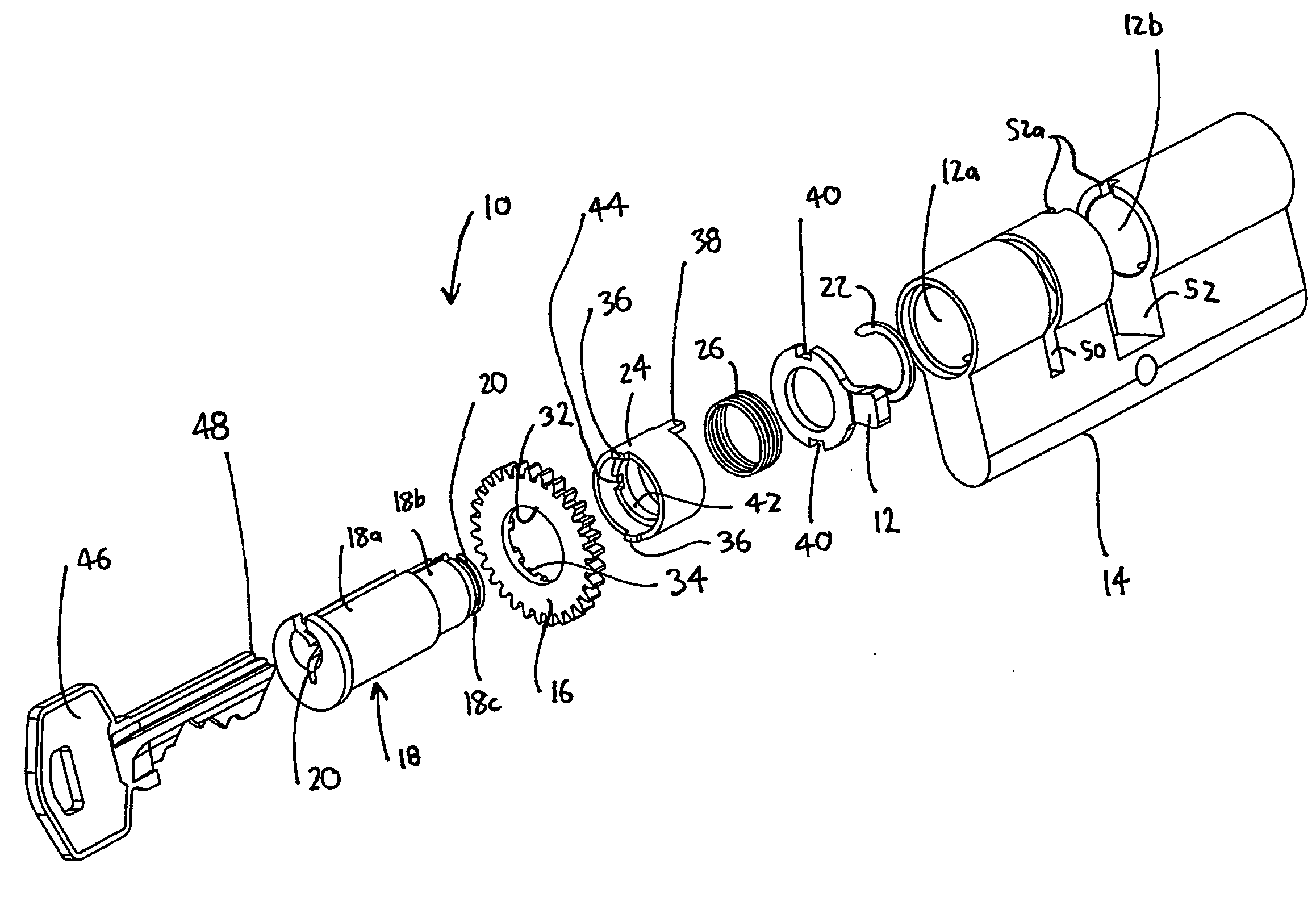
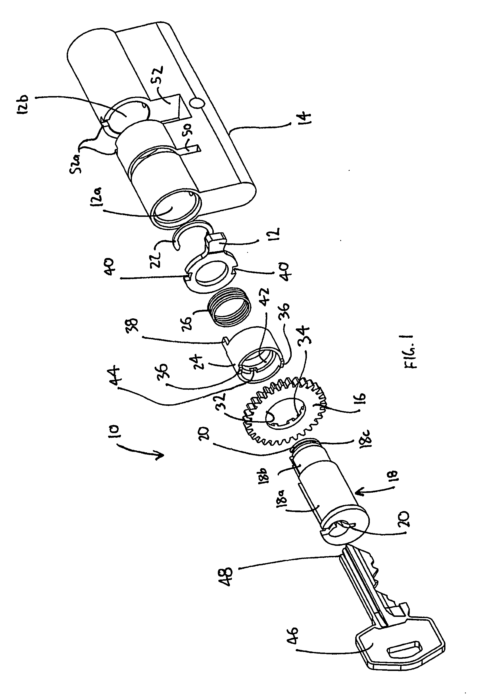
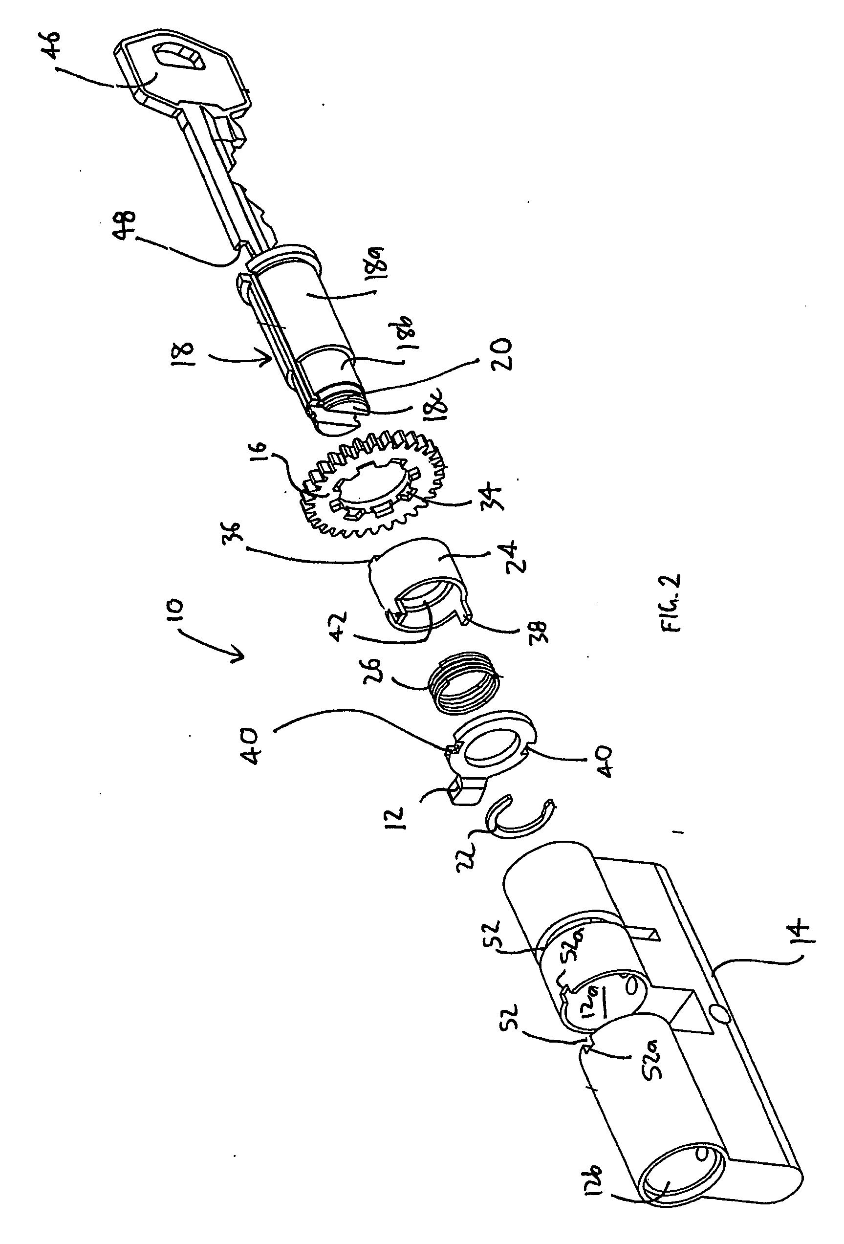
[0049]Turning firstly to FIG. 1, there is shown an embodiment of a lock assembly 10 suited for use with a powered actuator (not shown). The lock assembly 10 includes a steel cam 12 which operates a lock and latch mechanism (not shown) in a manner well understood by persons skilled in the art.

[0050]The lock assembly 10 includes a brass housing 14 having first and second spaced apart, opposed cylindrical recesses 12a and 12b.

[0051]The lock assembly 10 also includes a drive device, in the form of a steel drive gear 16, which is rotated by a spur gear (not shown) connected to an electric motor (not shown) by a gear reduction transmission (not shown).

[0052]The lock assembly 10 has a generally cylindrical, brass, first barrel part 18 in the first recess 12a. The barrel part 18 has a key slot 20 therein. A second barrel part (not shown) is received within the recess 12b and is operated only by a key in a manner well understood by persons skilled in the art.

[0053]The first barrel part 18 h...


PUM


Abstract

A lock assembly for use with a powered actuator includes a housing, a first barrel part, a torque transmitting member, a first cam, a drive device and a spring. The housing has at least a first axially extending recess therein. The first barrel part is within the first recess. The torque transmitting member is adapted for abutment and releasable rotational engagement with a key. The first cam is adapted to operate a lock or latch mechanism and for rotational movement with the torque transmitting member. The drive device is adapted for engagement with the powered actuator and releasable engagement with the torque transmitting member. The spring biases the torque transmitting member towards engagement with the drive device.

Description

FIELD OF THE INVENTION[0001]The present invention relates generally to a lock assembly and a method of operating a lock assembly and, more particularly, to a lock assembly suited for use with a powered actuator and a method for operating a powered lock assembly.BACKGROUND OF THE INVENTION[0002]Lock assemblies suitable for use with powered actuators are known and generally comprise a lock housing with two lock barrels therein. The lock assemblies are configured with one barrel able only to be manually driven by a key and the other barrel able only to be driven by the powered actuator. The lock assemblies are normally installed with the power driven barrel positioned on the outward side of a door and the key driven barrel positioned on the inward side of the door.[0003]A disadvantage of this arrangement is that, if the powered barrel is damaged, for example by vandalism or by unauthorised attempts to open the door, then any authorised person subsequently attempting to open the door wi...

Claims


Application Information

Patent Timeline
IPC IPC(8): E05B65/00E05B35/00
CPCE05B47/0012E05B47/0611E05B2047/002E05B2047/0026Y10S70/35Y10T70/7113Y10T70/7062Y10T70/5655Y10T70/7068Y10T70/5664Y10T70/7706
Inventor VELANDI, SAJANILIUK, ANDREY
Owner GAINSBOROUGH HARDWARE INDS
Learn More