Monodisperse droplet generation

a monodisperse droplet and droplet technology, applied in the field of multi-phase jet flow and microfluidics, can solve the problems of large size distribution of polydisperse droplets, unsuitable size distribution for many applications, and general unsuitability of polydisperse droplets for the formation of very small droplets, etc., to achieve the effect of higher speed and higher speed

Inactive Publication Date: 2010-07-08
EASTMAN KODAK CO
View PDF9 Cites 12 Cited by
  • Summary
  • Abstract
  • Description
  • Claims
  • Application Information

AI Technical Summary

Benefits of technology

[0022]The method of the present invention enables the passive regularisation of random Rayleigh jet break up.
[0023]Further, the method, by regularisation of jet break up, allows microfluidic monodisperse droplet formation at significantly higher speed than current art.
[0024]Further, the method enables the manufacture of monodisperse droplets or particles at significantly higher speed than current art.

Problems solved by technology

Most of this prior work to create emulsions and dispersions results in relatively polydisperse size distributions.
These techniques are not generally suitable for the formation of very small droplets.
However, membrane emulsification is one small scale technique using micron scale pores to form emulsions.
These methods whilst cheap typically produce polydisperse droplets unsuitable in size or size distribution for many applications.
Further, although in many cases sophisticated, these methods do not allow precise and arbitrary mixtures to be included within the droplets formed.
However as a method of production, the devices currently used are limited in flow speed to Capillary and Reynolds numbers less than about 1 and 10 respectively and therefore to droplet formation rates below about 20 kHz.

Method used


Image

  • Monodisperse droplet generation
  • Monodisperse droplet generation
  • Monodisperse droplet generation

Examples


Embodiment Construction

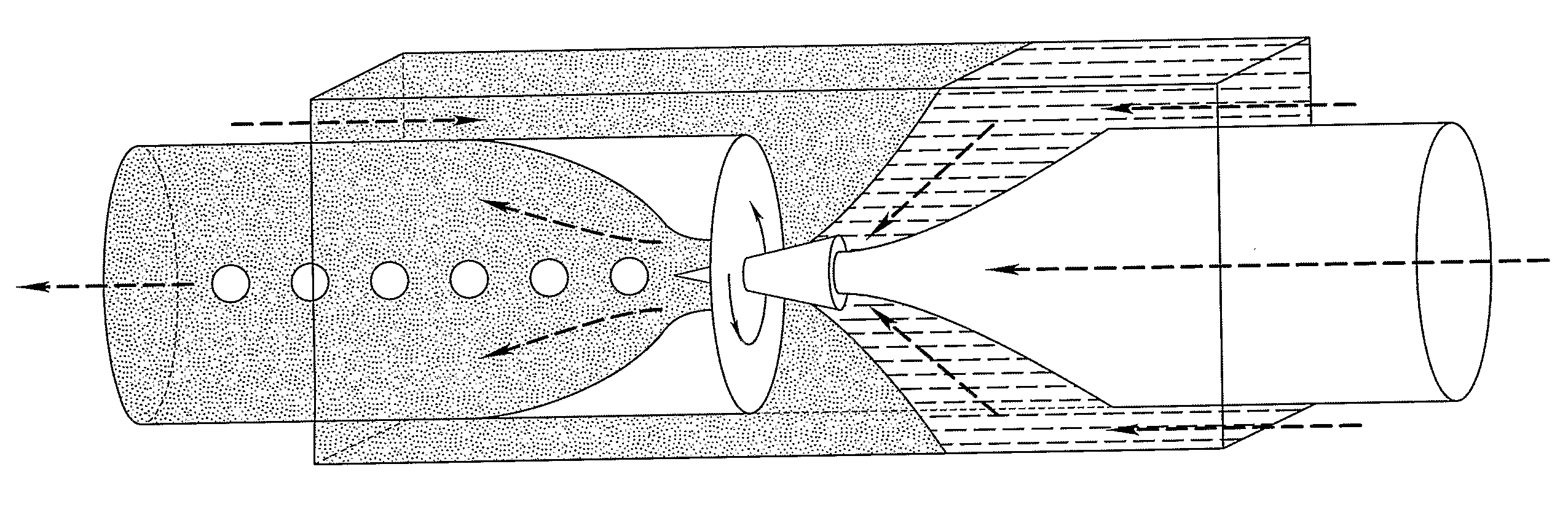
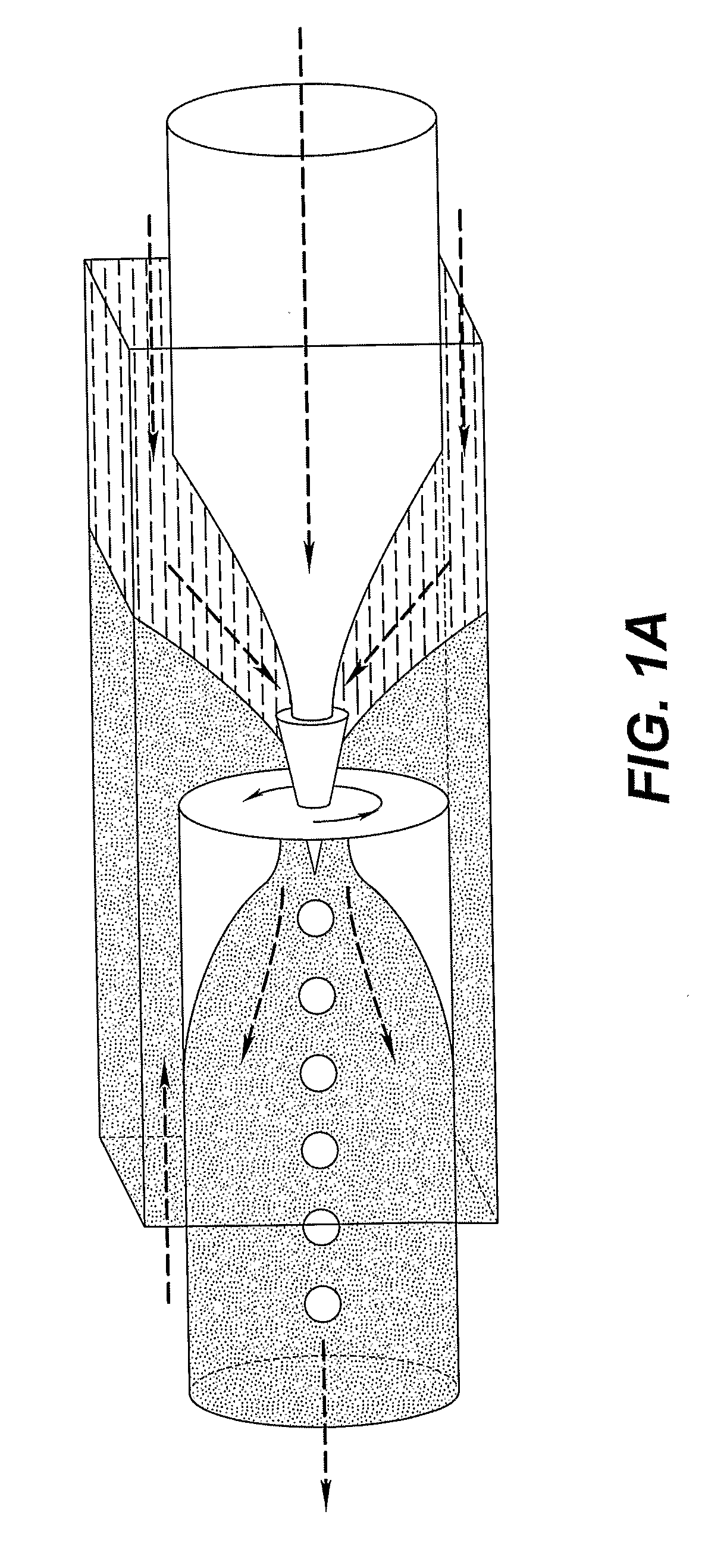
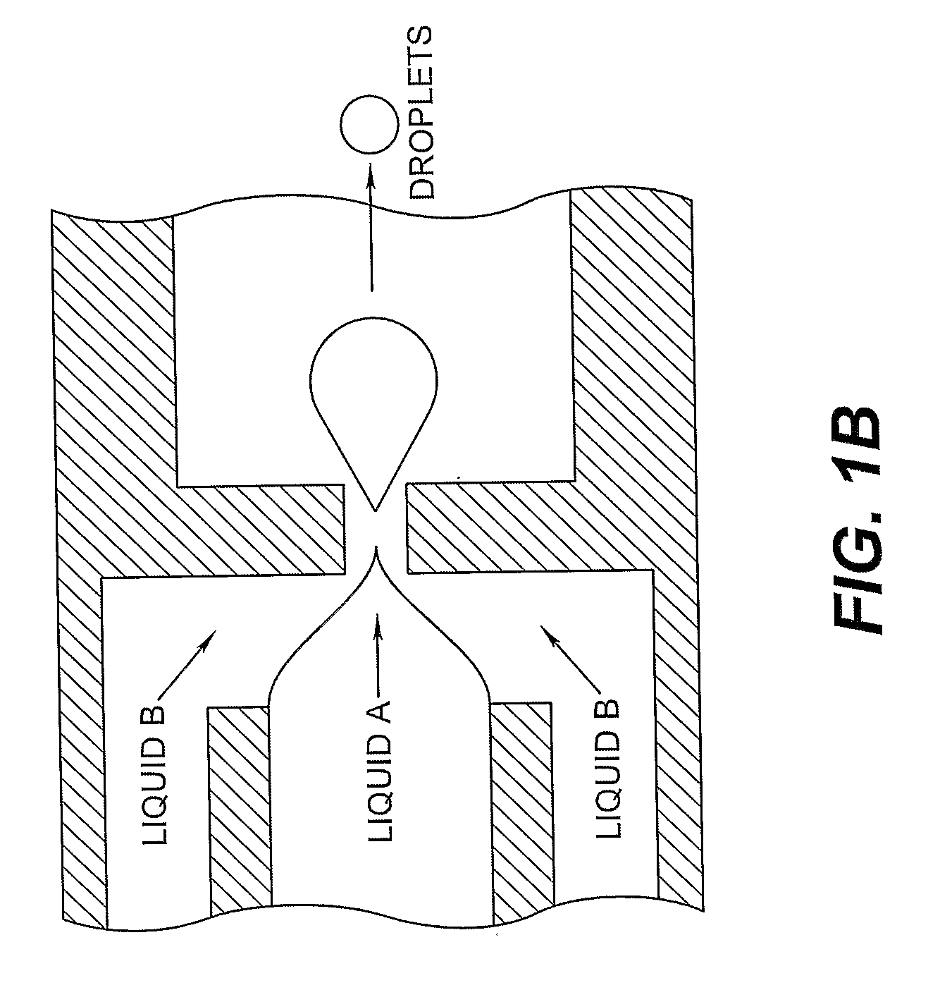
[0038]The ability to form a fluid jet of a first fluid within an immiscible second fluid within a microfluidic device is known in the art. Devices capable of this operation are shown in FIGS. 1a and 1b. However, the modes of operation usual for these devices are either a “geometry controlled” or a “dripping” mode, where monodisperse drops of the first fluid are directly formed. These modes are explained in S. L. Anna, H C. Mayer, Phys. Fluids 18, 121512 (2006). However, it is also well understood that as the fluid flow velocity increases the first fluid passes the orifice responsible for the “geometry controlled” or “dripping” modes and forms a jet in the area beyond. This jet then breaks up into droplets controlled predominantly by interfacial or surface tension. This jet break up mode is termed the Rayleigh-Plateau instability and produces polydisperse droplets of the first fluid.

[0039]It is a remarkable and hitherto unknown fact that the break up of a jet of a first fluid within ...


PUM

PropertyMeasurementUnit
Reynolds numbersaaaaaaaaaa
velocitiesaaaaaaaaaa

Abstract

A method of creating substantially monodisperse droplets comprising supplying a first fluid (1) and a second immiscible fluid (2) within a set of channels, the second fluid surrounding the first fluid and filling the channels to form a composite jet. The composite jet passes through an entrance channel (4) into a wider cavity (3), where the first fluid breaks into droplets (5), the resulting composite of droplets of the first fluid within the second fluid passing through an exit channel (6). The cross sectional area of the exit channel perpendicular to the flow is smaller than the cross sectional area of the cavity and the passage of a droplet of the first fluid out of the cavity via the exit perturbs the composite flow field within the cavity such that the incoming jet of the first fluid is perturbed.

Description

FIELD OF THE INVENTION[0001]This invention relates generally to multi phase jet flow and microfluidics, more specifically to microfluidics arranged to control the generation of droplets of a dispersed phase within another, immiscible, phase and their size distribution. In particular the invention relates to the generation of fluid droplets on a micro scale and in a multi phase system.BACKGROUND OF THE INVENTION[0002]The manipulation of fluids to form fluid streams of a desired configuration, discontinuous fluid streams, particles, dispersions, emulsions, etc., for the purposes of fluid delivery, analysis and product manufacture, such as photographic silver halide emulsions and dispersions, is a relatively well studied art. Most of this prior work to create emulsions and dispersions results in relatively polydisperse size distributions. Recently highly monodisperse gas bubbles have been produced using a technique referred to as capillary flow focussing. In this technique, gas is forc...

Claims


Application Information

Patent Timeline
Patent Type & Authority Applications(United States)
IPC IPC(8): B05B7/04
CPCB01F3/0807B01F5/0646B01F5/0654B01F13/0062B01F23/41B01F25/4337B01F25/433B01F33/3011
Inventor CLARKE, ANDREW
Owner EASTMAN KODAK CO
Why Eureka
Try Eureka