Engine assembly for aircraft with sliding nancelle

a technology of sliding nacelle and engine, which is applied in the direction of machines/engines, power plant inspection panels, air-flow influencers, etc., can solve the problems of insufficient acoustic treatment of the nacelle, inability of the nacelle to attenuate the deformation of the turbojet, and insufficient structural capacity of the nacelle to achieve the effect of reducing the bending of the turbojet, reducing the potential friction, and high stiffness of the mobile na

Active Publication Date: 2010-07-08
AIRBUS OPERATIONS (SAS)
View PDF22 Cites 29 Cited by
  • Summary
  • Abstract
  • Description
  • Claims
  • Application Information

AI Technical Summary

Benefits of technology

[0022]The special form of this mobile nacelle portion has several advantages, including that it is capable of resisting higher forces than can be resisted by the assembly of two articulated C-covers encountered in prior art. Therefore, the invention provides a genuine solution to the problem of turbojet deformation, given that the high stiffness of the mobile nacelle portion contributes to limiting these deformations.
[0023]Consequently, this reduces bending of the turbojet and therefore generates a significant reduction in the potential friction between the rotating blades of the compressor and the turbine and the central casing of the engine. In particular, the reduction in bending makes it possible to apply smaller nominal clearances between the blades and the casing, which advantageously results in a gain in the global performance of the aircraft and a significant limitation to losses of efficiency.
[0024]Furthermore, the continuous nature of this mobile nacelle portion covering 360° around a cross section of the turbojet advantageously results in better acoustic insulation than was possible in the past with the assembly of two C-shaped covers, because there is no longer any discontinuity of material around the hoop direction of the nacelle. In particular, the wall(s) of the mobile nacelle portion may be provided with an acoustic lining that extends continuously or almost continuously around 360°, further improving the reduction in noise escaping from the nacelle.
[0025]The nacelle thus made can also facilitate maintenance due to the simplicity of its dynamics for a mass less than the mass of nacelles k

Problems solved by technology

Although this design is very commonly used, it has some disadvantages, including the lack of stiffness of the nacelle, and the fact that the nacelle is not optimally treated acoustically.
The structural capacity of the nacelle to attenuate deformations of the turbojet is intrinsically limited by the force concentration at closing elements such as the hinges, locks, compression rods and other offset actuators or locks.
Thus, the nacelle cannot satisfactorily resist deformations of the turbojet, and particularly the variable magnitude of longitudinal bending, namely bending due to a torque applied about a transverse direction of the aircraft, if its stiffness is limited.
When such longitudinal bending occurs, particularly during the aircraft takeoff and landing pha

Method used


Image

  • Engine assembly for aircraft with sliding nancelle
  • Engine assembly for aircraft with sliding nancelle
  • Engine assembly for aircraft with sliding nancelle

Examples


Embodiment Construction

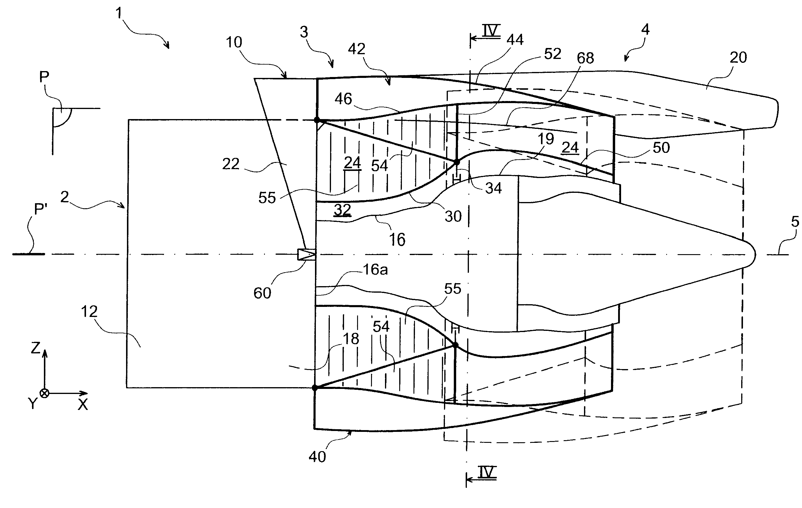
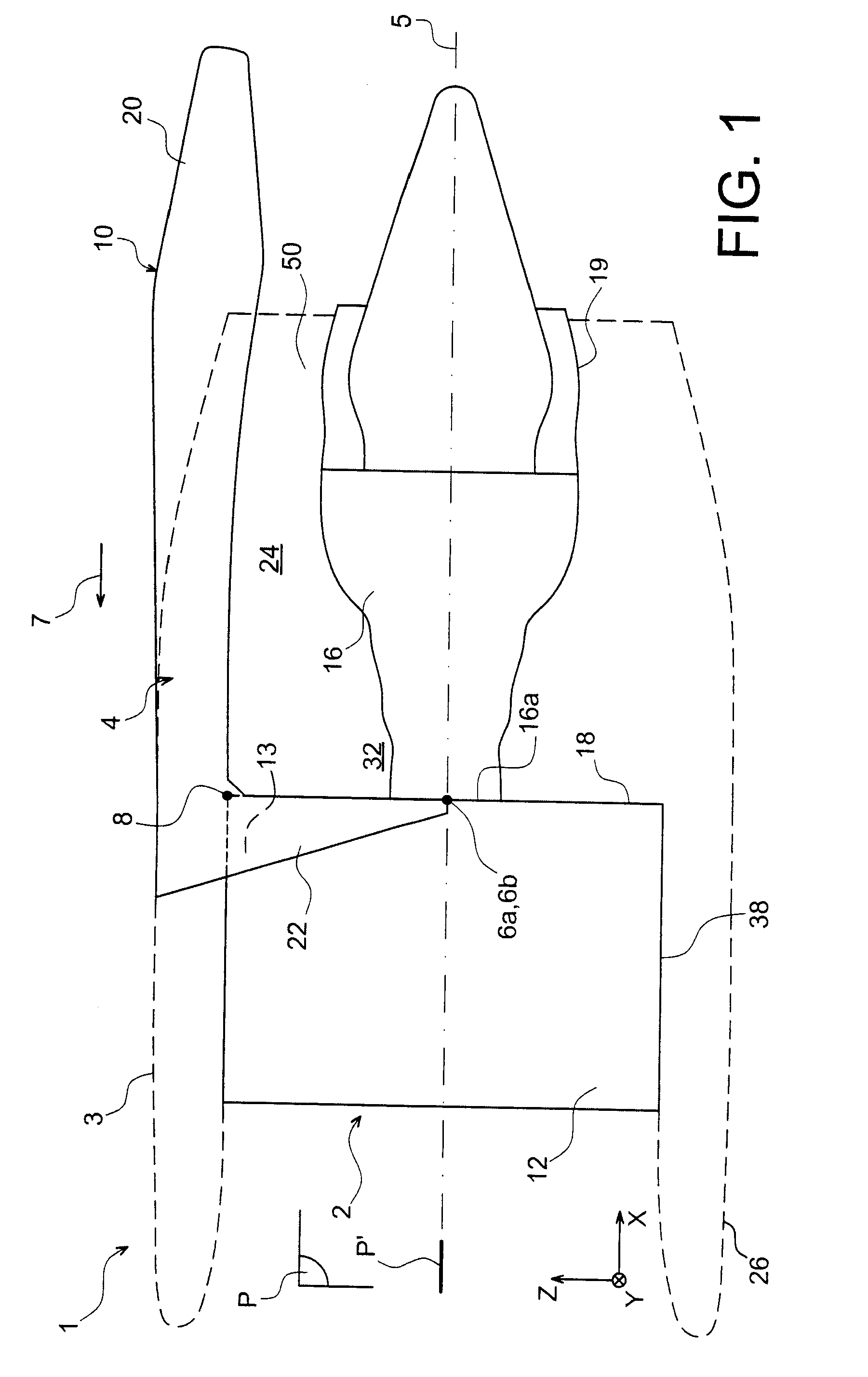
[0054]FIG. 1 shows an engine assembly 1 for an aircraft according to a preferred embodiment of this invention, this assembly 1 being designed to be fixed under an aircraft wing (not shown).

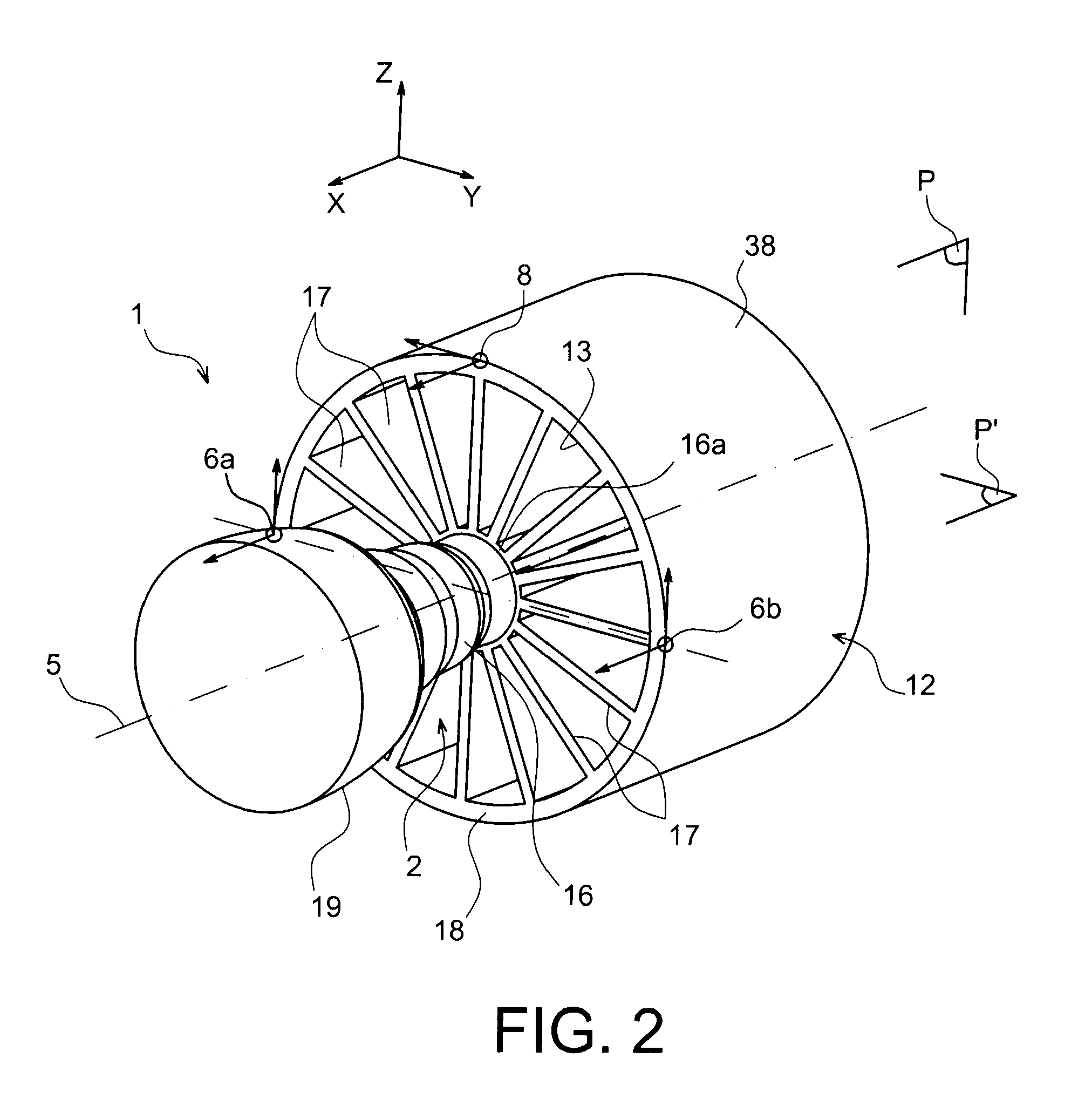
[0055]Globally, the engine assembly 1 comprises a turbojet 2, a nacelle 3 shown diagrammatically in dashed lines, an attachment pylon 4, and a plurality of engine attachments 6a, 6b, 8 fixing the turbojet 2 under this pylon 4 (the attachment 6b being hidden by the attachment 6a in this FIG. 1). Note for information that the attachment pylon 4 comprises another series of attachments (not shown) used to suspend this assembly 1 under the aircraft wing.

[0056]In the following description, by convention X is the direction parallel to a longitudinal axis 5 of the turbojet 2, also corresponding to a longitudinal direction of the engine assembly and the pylon, Y is the transverse direction for this same turbojet 2 also corresponding to a transverse direction of the engine assembly and the pylon, and Z is t...


PUM


Abstract

An aircraft engine assembly including a turbojet, a turbojet attachment pylon, and a nacelle mounted on the attachment pylon and surrounding the turbojet. The nacelle includes at least one mobile nacelle portion forming a single piece envelope all around a section of the turbojet, this mobile nacelle portion being mounted free to slide on the attachment pylon so that it can be moved from the forward position in the aft direction, and vice versa.

Description

TECHNICAL DOMAIN[0001]This invention relates in general to an aircraft engine assembly of the type including a turbojet, an attachment pylon and a nacelle mounted on the attachment pylon and surrounding the turbojet.[0002]This type of attachment pylon, also called an “EMS” (Engine Mounting Structure), can for example be used to suspend a turbojet below the aircraft wing, or to mount this turbojet above this wing, or to mount a turbojet on an aft part of the fuselage.STATE OF PRIOR ART[0003]The attachment pylon for such an engine assembly is designed in a known manner to form the connection interface between a turbojet type engine and an aircraft wing equipped with this assembly. It transmits forces generated by its associated engine to the structure of this aircraft, and also enables routing of fuel, electrical, hydraulic and air systems between the engine and the aircraft.[0004]In order to transmit forces, the pylon comprises a rigid structure, for example a “box” type structure, i...

Claims


Application Information

Patent Timeline
IPC IPC(8): B64D27/02B64C1/40B64D29/08F02K1/72
CPCB64D29/08B64D33/04F02C7/20F05D2250/41Y02T50/671F05D2260/96F02K1/72Y02T50/60
Inventor JOURNADE, FREDERICLAFONT, LAURENT
Owner AIRBUS OPERATIONS (SAS)
Why Eureka
Try Eureka