Communication across an inductive link with a dynamic load

a dynamic load and inductive link technology, applied in the field of wireless communication, can solve the problems of increasing power loss associated with communication, increasing power loss, and increasing reliability, and achieve the effect of reducing the amount of power lost, consuming more power, and minimizing the size of the load shi

Active Publication Date: 2010-07-08
PHILIPS IP VENTURES BV
View PDF36 Cites 122 Cited by
  • Summary
  • Abstract
  • Description
  • Claims
  • Application Information

AI Technical Summary

Benefits of technology

[0007]The dynamic load configuration can be configured to create a sufficient difference in reflected impedance or load shift from the other load configuration so that the inductive power supply can receive communication. The load shift can account for the amount of power delivered to the remote device and ensure that that the load shift is sufficient for that amount of power. The dynamic load configuration can also be configured to minimize the amount of power lost due to communication with the inductive power supply. A larger load shift consumes more power, therefore minimizing the size of the load shift also minimizes power losses. It should be noted that the secondary circuit may be tuned to resonance by the primary and may also include a series and / or parallel resonant capacitor(s).
[0008]In one embodiment, the dynamic load configuration is configured by toggling between the dynamic load configuration and another load configuration while gradually increasing the resistance of the dynamic load configuration until the inductive power supply receives the communication. The dynamic load configuration where the inductive power supply first receives communication is the load configuration with the smallest load shift sufficient for communication, which also equates to the dynamic load configuration capable of communication with the least power losses.
[0009]By dynamically changing at least one of the load configurations based on the amount of power delivered to the remote device, significant power savings can be realized.

Problems solved by technology

There are a number of challenges with backscatter modulation and similar techniques that occur within inductive power supply systems that are not as problematic in traditional RFID systems.
As the amount of power drawn by or delivered to the secondary increases, the power losses associated with communicating increase.
Further, power losses are often amplified because the communication resistor for a remote device is typically selected during manufacture to account for worse case scenarios.
This additional reliability often comes at the price of additional power losses during communication, even in normal or optimal conditions.

Method used


Image

  • Communication across an inductive link with a dynamic load
  • Communication across an inductive link with a dynamic load
  • Communication across an inductive link with a dynamic load

Examples


Embodiment Construction

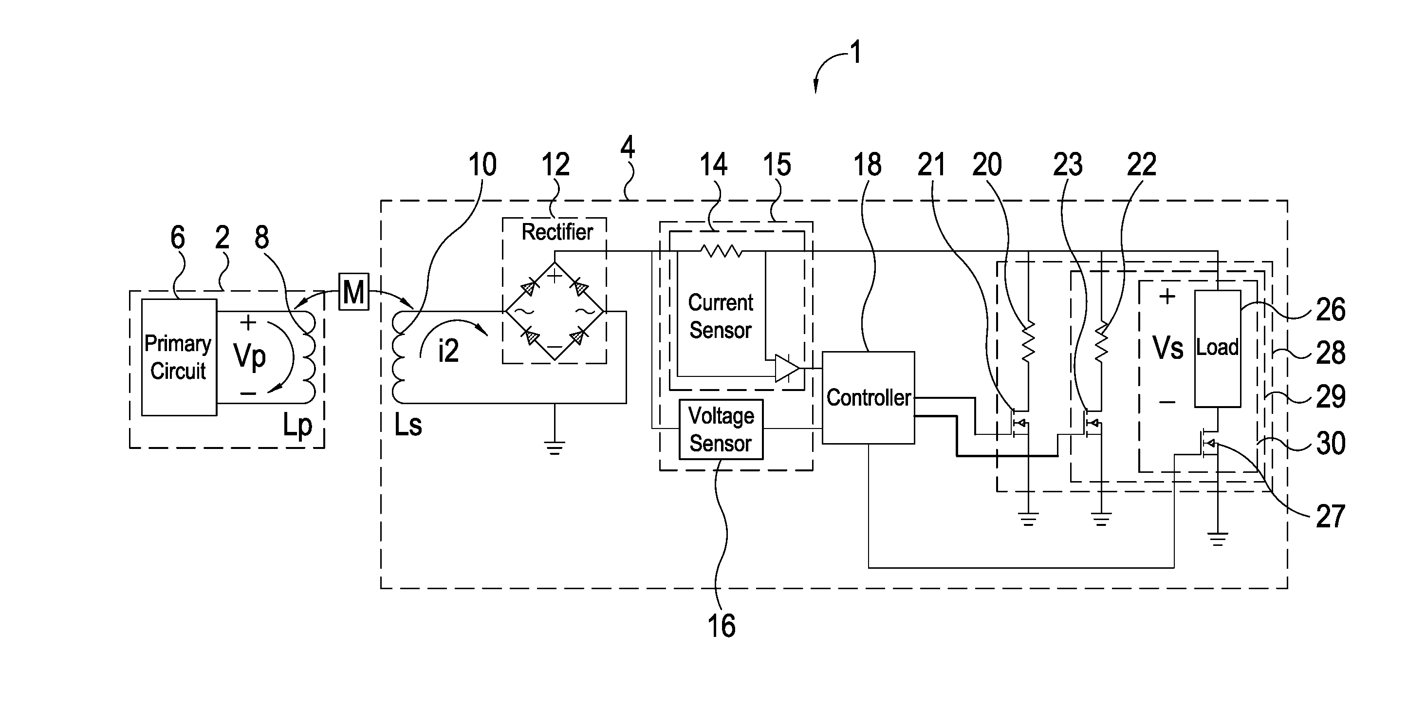
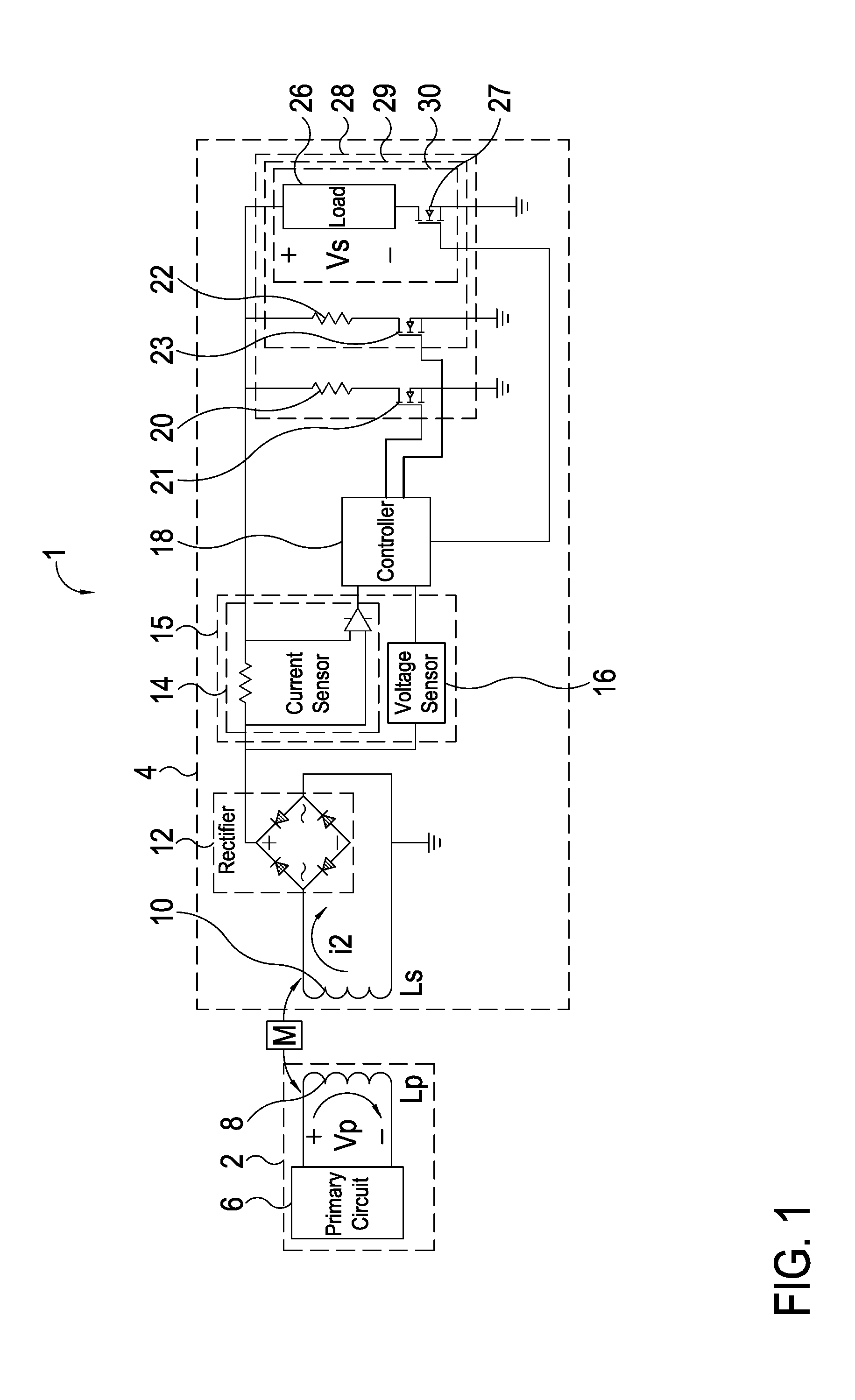
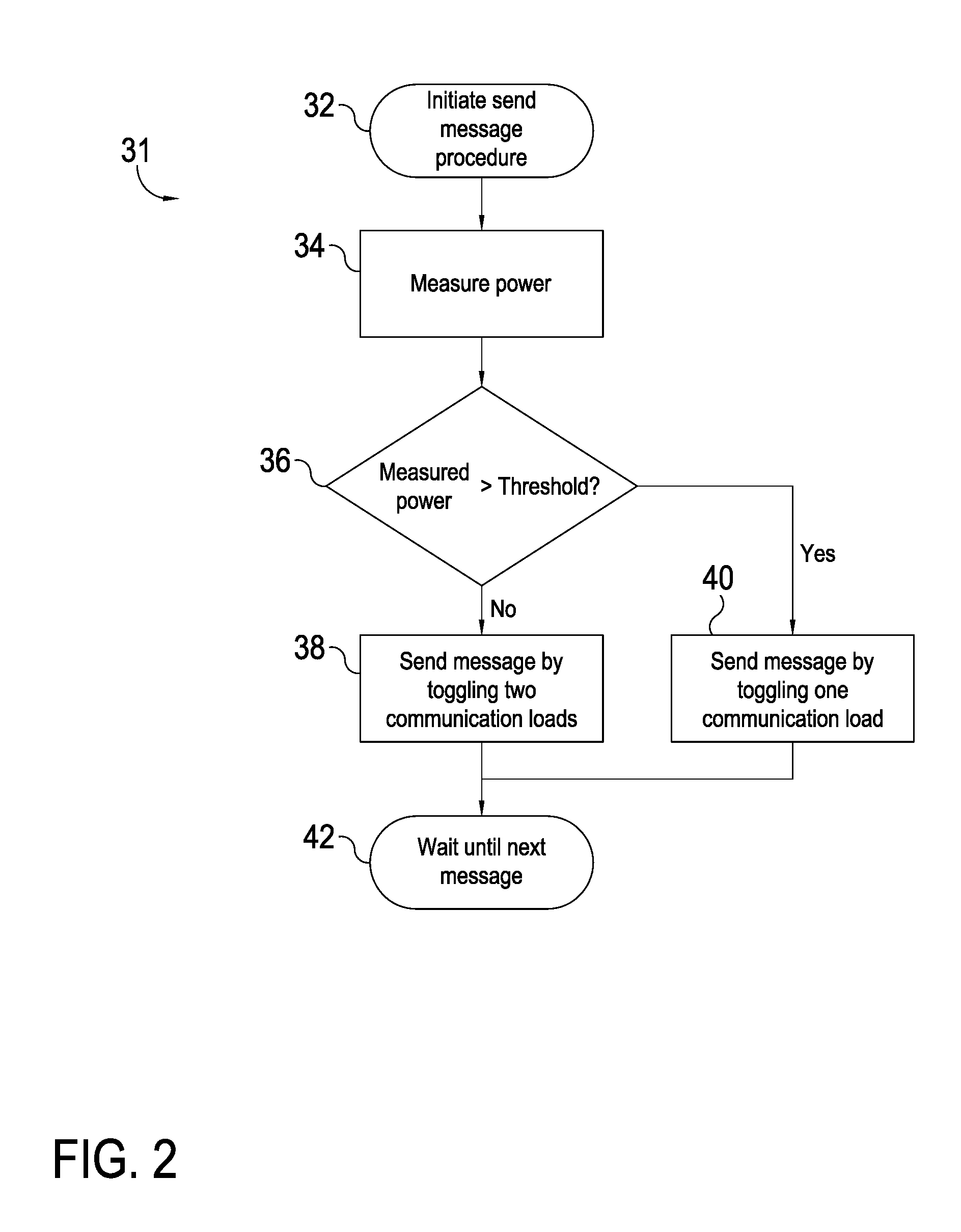
[0014]An inductive power supply system in accordance with one embodiment of the present invention is shown in FIG. 1 and generally designated 1. The inductive power supply system includes an inductive power supply 2 and a remote device 4. The remote device 4 has multiple communication load configurations, at least one being a dynamic communication load configuration. The remote device 4 toggles between the communication load configurations to communicate with the inductive power supply 2. A sensor in the remote device 4 detects the amount of power that the inductive power supply 2 delivers to the remote device 4. A controller 18 in the remote device is capable of configuring the dynamic communication load configuration based on the detected power. The controller in the remote device is also capable of toggling between the different communication load configurations to communicate with the inductive power supply 2.

[0015]The present invention is suitable for use with most inductive po...


PUM


Abstract

The present invention provides a load used for communication in a remote device having a dynamic communication load configuration. In one embodiment, the dynamic communication load configuration vanes as a function of a characteristic of power in the remote device. The remote device toggles between load configurations to communicate with the inductive power supply. A sensor in the remote device detects a characteristic of power in the remote device and configures the communication load based on the sensor output. In another embodiment, the remote device adjusts the dynamic communication load configuration in the remote device in response to a failure to receive a response from the inductive power supply.

Description

BACKGROUND OF THE INVENTION[0001]The present invention relates to wireless communication, and more particularly to minimizing power losses during wireless communication.[0002]Backscatter modulation is a common communication technique in many RFID applications. Backscatter modulation can be used in a passive RFID tag to send data back to an RFID reader without using a transmitter. Instead, communication is accomplished by repeatedly shunting a coil in the RFID tag through a transistor, the shunting causes slight fluctuations in the RFID reader's carrier amplitude. As the secondary winding is momentarily shunted, the primary winding experiences a momentary voltage drop. The RFID reader can detect this voltage drop and interpret that data as a bit. Bits can be strung together by systematically shunting the secondary winding. The data bits can be encoded by a variety of encoding algorithms that may affect error recovery, cost of implementation, bandwidth, or synchronization capability.[...

Claims


Application Information

Patent Timeline
Patent Type & Authority Applications(United States)
IPC IPC(8): H02J17/00
CPCG06K19/0707G06K19/0712G06K19/07749H02J5/005H02J17/00H02J7/025H04B5/0037H04B5/0081H02J50/10H02J50/80H04B5/0031H02J50/90
Inventor BAARMAN, DAVID W.SCHWANNECKE, JOSHUA K.MOLLEMA, SCOTT A.NORCONK, MATTHEW J.
Owner PHILIPS IP VENTURES BV
Why Eureka
Try Eureka