Air sampling system having inline flow control switch

Active Publication Date: 2010-07-08
VALTEK ASSOC INC
View PDF18 Cites 39 Cited by
  • Summary
  • Abstract
  • Description
  • Claims
  • Application Information

AI Technical Summary

Benefits of technology

[0022]It is still another object of the present invention to provide a system and method that takes advantage of wireless technology t

Problems solved by technology

However, that is not always the case, as other operations within those industries may generate contaminants that are above acceptable levels and, therefore, must be prevented from escaping the clean room without treatment.
Negative pressure rooms are often used when there is a concern that contaminants in the air may pose a potential health threat to human health in adjacent spaces, or the environment.
The patent states that previous sampling devices could not achieve a constant volumetric air flow of better than ±30% relative to a nominal or set-point fl

Method used


Image

  • Air sampling system having inline flow control switch
  • Air sampling system having inline flow control switch
  • Air sampling system having inline flow control switch

Examples


Embodiment Construction

[0043]Several preferred embodiments of the invention are described for illustrative purposes, it being understood that the invention may be embodied in other forms not specifically shown in the drawings.

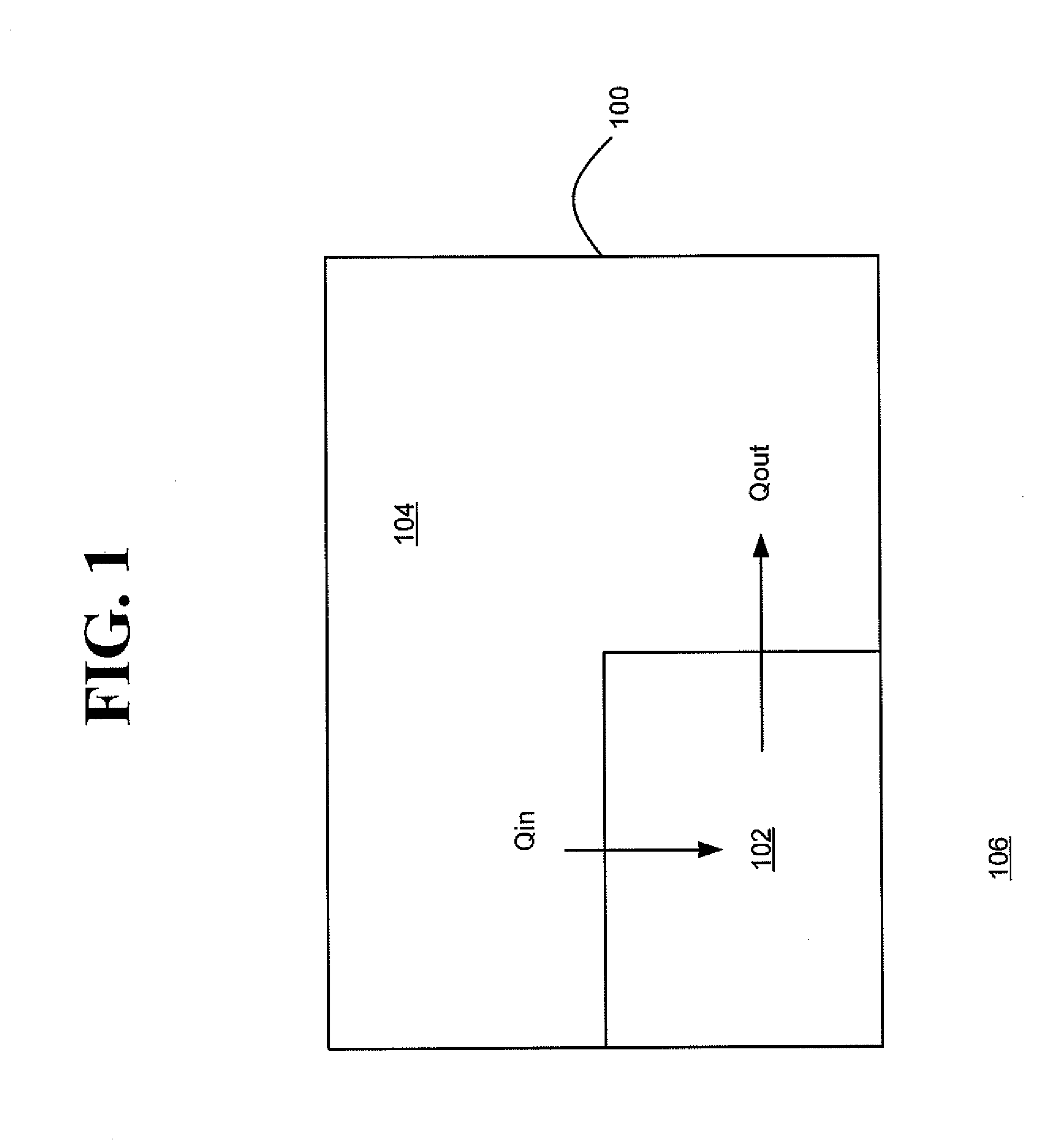
[0044]Turning first to FIG. 1, shown therein is a schematic of an exemplary facility 100 having one or more clean rooms 102 therein. The clean room 102 is adjacent a space 104 and the outdoor atmosphere 106. The adjacent space 104 may be any one or more rooms within the same facility 100 that the clean room 102 is located and that adjoins the clean room 102, such as, for example, a separate manufacturing room, another clean room, a finish and fill room, a research laboratory, or offices. The clean room 102 and adjacent space 104 are separated by a divider, such as a wall.

[0045]The clean room 102 in the exemplary facility 100 is capable of being maintained at an air pressure P1 that is less than the air pressure P2 of the adjacent space 104, and also less than atmospheric air pressure...


PUM


Abstract

A sampling system for quantifying the amount of contaminants in a controlled environment within a facility. The system has an air sampling devices each associated with a respective flow switch module, both within the controlled environment, and a first and second controller located outside the controlled environment. The first controller is in flow communication with the air sampling devices. The first controller is also in flow communication with the flow switch modules and controls a vacuum source to draw a predetermined volume of air through the at least one air sampling device via the at least one flow switch module at a desired flow rate. The flow switch module detects when the actual flow rate falls below or above a predetermined value, and generates an alarm.

Description

RELATED APPLICATIONS[0001]This application is a continuation-in-part of application Ser. No. 12 / 068,483, filed Feb. 7, 2008, for “System and Method for Air Sampling in Controlled Environments,” which is hereby incorporated by reference.BACKGROUND OF THE INVENTION[0002]1. Field of the Invention[0003]The present invention relates to devices and methods for collecting air samples in indoor environments. In particular, the present invention relates to devices and methods for collecting, processing and analyzing air samples in clean rooms, electrically and automatically controlling the sampling equipment, and calibrating the same.[0004]2. Description of the Related Art[0005]Clean rooms found in manufacturing, research, and other facilities are typically classified into two broad categories based on the static air pressure inside the rooms relative to atmospheric pressure and / or the air pressure in spaces adjacent the clean rooms. A positive air pressure room is maintained at an absolute ...

Claims


Application Information

Patent Timeline
IPC IPC(8): G08B21/00G01N1/20G01N1/14
CPCG01N1/26G01N2035/00881
Inventor CALIO, ROSARIO S.
Owner VALTEK ASSOC INC
Why Eureka
Try Eureka