LED street lamp

Inactive Publication Date: 2010-07-08
OPTO TECH
View PDF4 Cites 14 Cited by
  • Summary
  • Abstract
  • Description
  • Claims
  • Application Information

AI Technical Summary

Benefits of technology

[0012]The LED street lamp of the present invention has other heat dissipation features, including a plurality of heat dissipation slots and a plurality of lateral side heat di

Problems solved by technology

The state-of-the-art LED street lamp is generally incapable of adjustment of illumination angle and brightness uniformity in accordance with different sites of installation.
On the other hand, due to the poor heat resistance of the LEDs, the heat generated by the LEDs during thereof operation must be dissipated by employing a heat dissipation device so as to maintain the LEDs in a proper temperature range for giving off light without bein

Method used


Image

  • LED street lamp
  • LED street lamp
  • LED street lamp

Examples


first embodiment

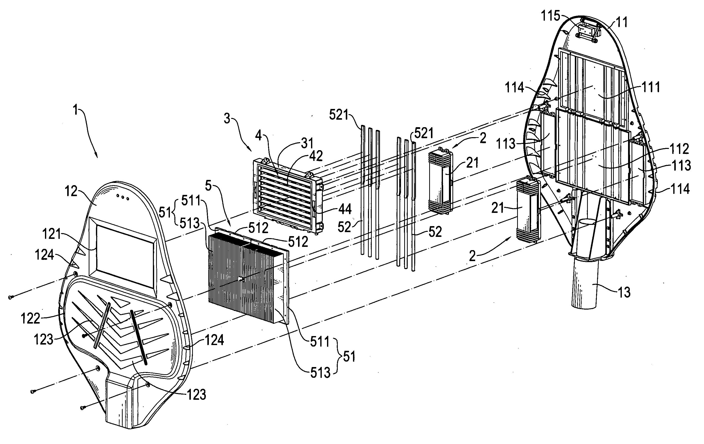
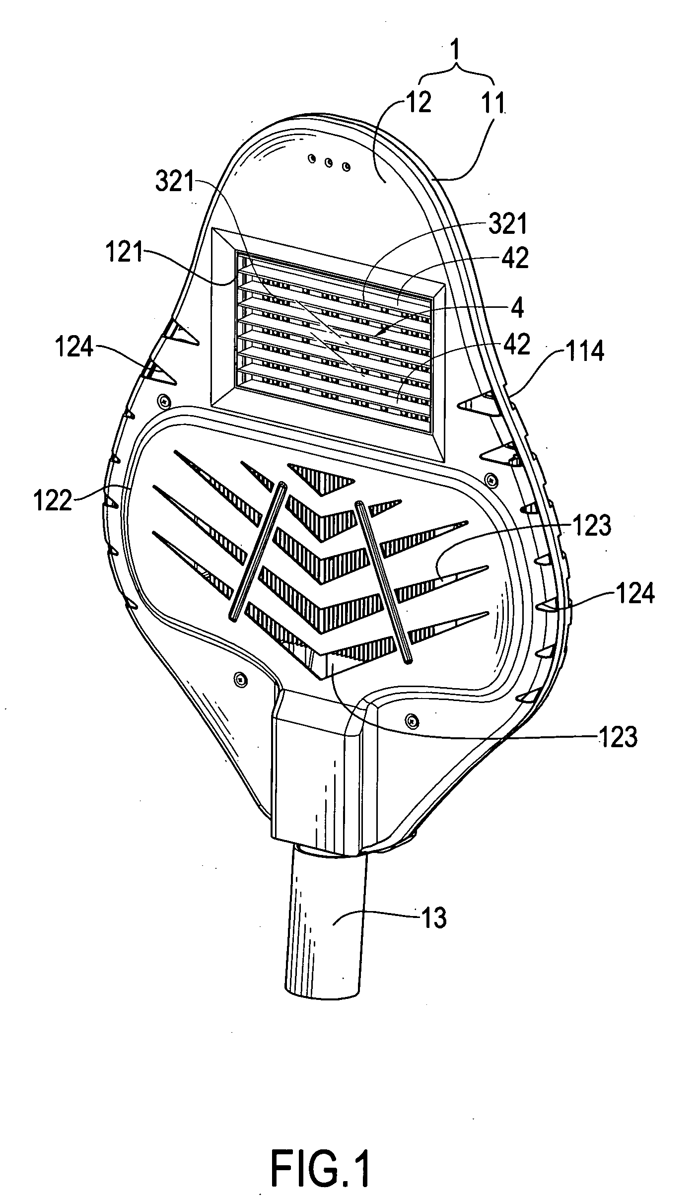
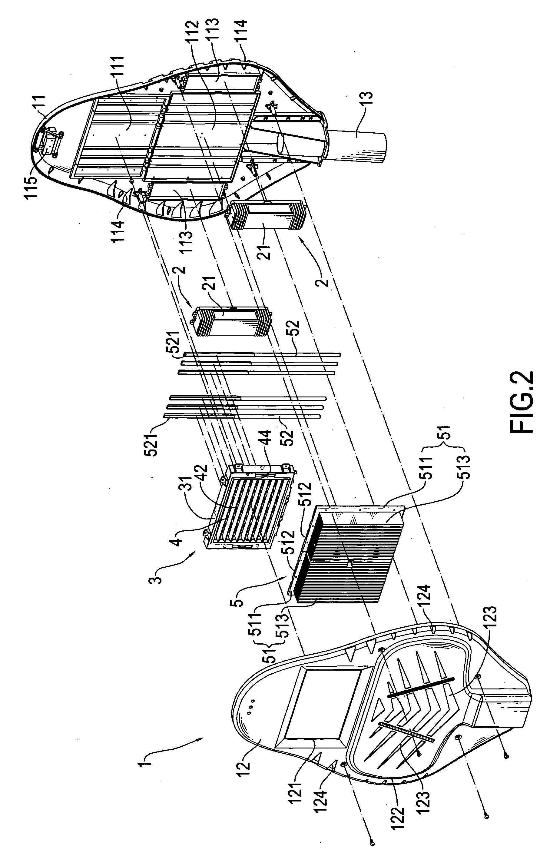
[0029]Reference is now made to the LED module 3 shown in FIGS. 3 and 4. The frame 31 of the LED module has a front side to which a light-transmitting board (not labeled) is attached. The light regulation mechanism 4 is set between the frame 31 and the circuit board 32. The light regulation mechanism 4 comprises a pair of support racks 41, a plurality of reflector plates 42, a link bar 43, and at least one control element 44. In the embodiment shown in FIG. 3, two roller-like control elements 44 are provided. Each reflector plate 42 has two opposite ends each having a central position 421 and an eccentric position 422. Each reflector plate 42 is arranged between and pivotally mounted to the support racks 41 through the central positions 421 of the ends thereof. The two control elements 44 each have a pivot axle 441 and the two pivot axles 441 are respectively coupled to the central positions 421 of the two ends of one of the reflector plates 42, whereby the control elements 44 may be...

second embodiment

[0032]Reference is now made to the LED module 3 illustrated in FIG. 6. The second embodiment LED module 3 comprises a light regulation mechanism 6 that is arranged between the frame 31 and the circuit board 32 and the circuit board 32 carries a plurality of LEDs 32 that is arranged in a row by row manner so as to form multiple rows of LEDs on the circuit board 32. Since this arrangement makes illumination that is brighter in a middle portion but darker in opposite side portions, the interference of light realized by the light regulation mechanism 6 is employed to provide light compensation for the opposite side portions. As shown in FIG. 8, the light regulation mechanism 6 comprises a plurality of reflector plates 61 for light compensation. To prevent excessive brightness after the compensation of light, at least one of the LED rows is selectively set as vacant row, such as row 65 for consideration of brightness. To not shield the emission light of the adjacent LED row, the reflecto...


PUM


Abstract

A light-emitting diode (LED) street lamp is applicable for street lighting. The LED street lamp includes a casing, an LED module, and a heat dissipation module. The LED module and the heat dissipation module are arranged inside the casing. The LED module includes a frame, a circuit board carrying a plurality of LEDs, and a light regulation mechanism. The frame and the circuit board are set opposing each other with the light regulation mechanism arranged therebetween to interfere with emission light from the LEDs. The emission light, after being interfered with, is projected outside the casing to realize lighting. The heat dissipation module is in physical engagement with the LED module to remove heat generated by the LEDs. As such, the LED street lamp is provided with a broader range of illumination angle and more uniform brightness, so that the same LED street lamp is applicable to various sites and the heat generated by the LEDs can be efficiently dissipated.

Description

FIELD OF THE INVENTION[0001]The present invention relates to a light-emitting diode (LED) street lamp, and in particular to a LED street lamp that comprises an LED module that contains therein a light regulation mechanism and that is applicable for street lighting.BACKGROUND OF THE INVENTION[0002]Due to the advantages of high brightness and power saving, light-emitting diodes (LEDs) are widely used in various lighting devices, of which an example is an LED street lamp for street lighting.[0003]However, the LED street lamp may be set at different heights for illumination at different sites. For example, a LED street lamp in a park has a quite different height of installation from that in an ordinary street. Different illumination height of the LED street lamp affects the illumination angle and brightness uniformity of the LED street lamp. The state-of-the-art LED street lamp is generally incapable of adjustment of illumination angle and brightness uniformity in accordance with differ...

Claims


Application Information

Patent Timeline
IPC IPC(8): F21V29/00
CPCF21V11/04F21V11/16F21V11/18F21V29/004F21W2131/103F21V29/763F21Y2101/02F21V29/006Y02B20/72F21V29/717F21W2131/105F21Y2115/10
Inventor MO, YUN-CHIANGLIAO, CHIA-HUACHEN, YI-CHUNHUANG, YEN-YUCHUANG, CHIA-HSIANG
Owner OPTO TECH
Why Eureka
Try Eureka